Method of manufacturing divided cores for a stator

a technology of divided cores and stators, which is applied in the direction of stator/rotor bodies, manufacturing stators/rotor bodies, and applying solid insulation, etc., can solve the problems of reducing the production efficiency of stators or motors, reducing the size of stators, and difficult to improve the winding efficiency of wires, so as to avoid short circuits and reduce the circumferential length of stators , the effect of preventing wires

Active Publication Date: 2019-01-17
HONDA MOTOR CO LTD
View PDF9 Cites 2 Cited by
  • Summary
  • Abstract
  • Description
  • Claims
  • Application Information

AI Technical Summary

Benefits of technology

[0008]If the wire is wound at a low speed, the amount of movement of the electromagnetic coil in the diametrical inward direction of the stator can be reduced. However, in this case, the winding efficiency of the wire, and hence the production efficiency of the stator or the motor, is lowered.
[0027]In addition, since there is no need to reduce the winding speed of the wire, sufficient winding efficiency is ensured, and the production efficiency of the divided cores for the stator as well as the stator itself is maintained.

Problems solved by technology

However, in this case, the winding efficiency of the wire, and hence the production efficiency of the stator or the motor, is lowered.
In the forgoing manner, in the method of manufacturing the divided cores for a stator according to the conventional technique, there is an inconvenience in that it is difficult to improve winding efficiency of the wire while at the same time reducing the size of the stator.

Method used


Image

  • Method of manufacturing divided cores for a stator
  • Method of manufacturing divided cores for a stator
  • Method of manufacturing divided cores for a stator

Examples


Embodiment Construction

[0036]A preferred embodiment in relation to a method of manufacturing divided cores for a stator according to the present invention will be described in detail below with reference to the accompanying drawings. In the description given below, the divided cores for a stator are also referred to simply as divided cores.

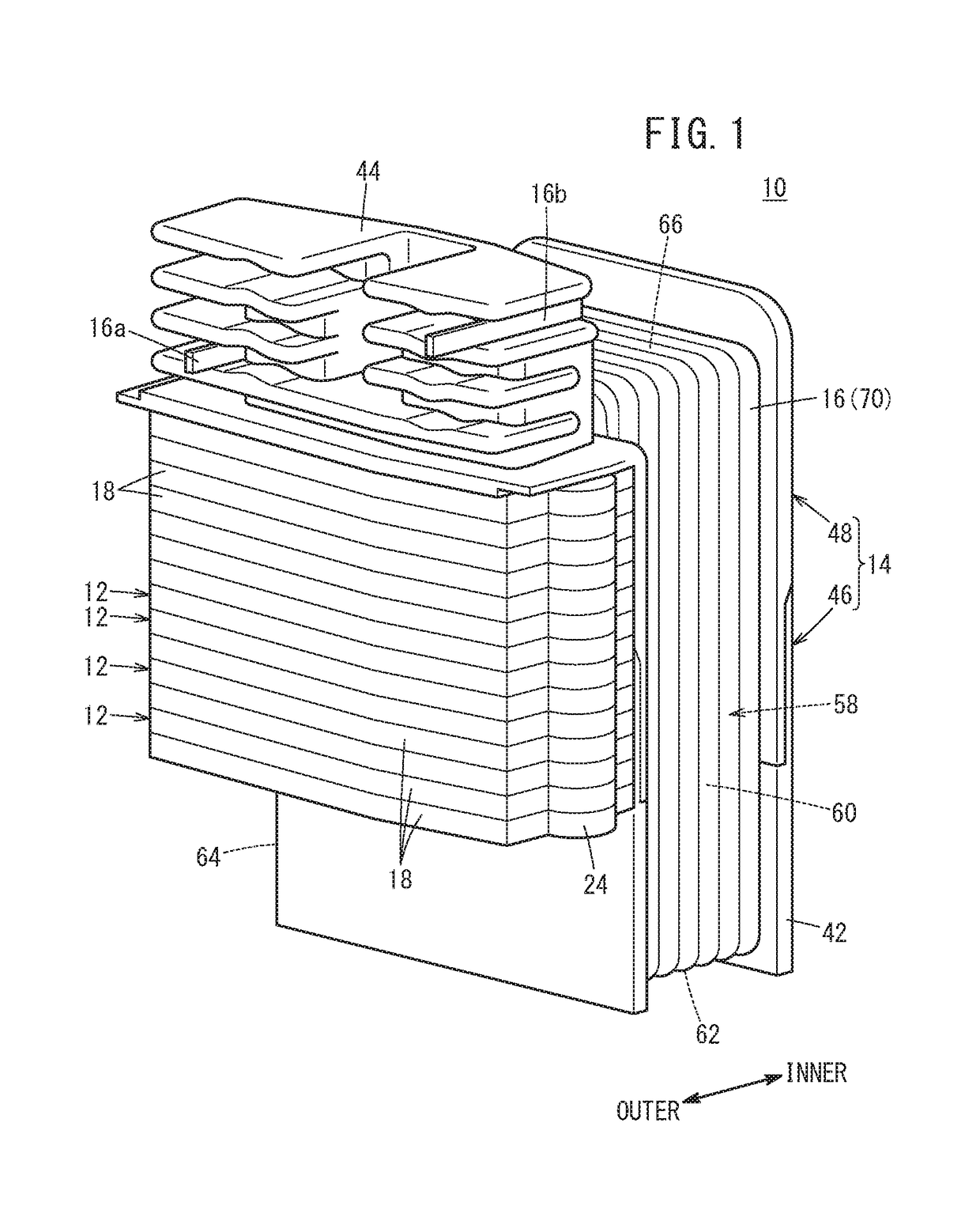
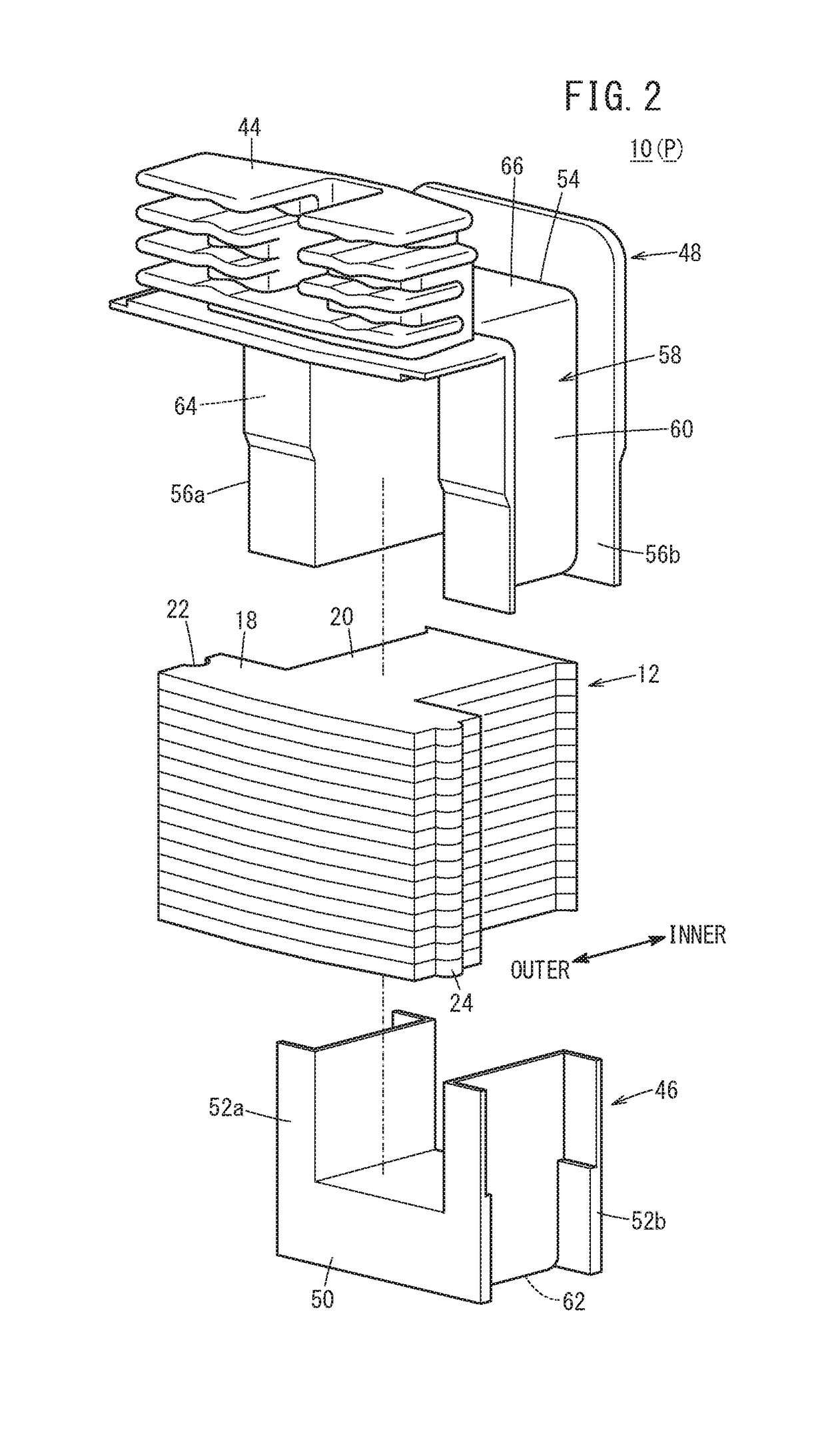
[0037]First, the divided cores that constitute the stator will be described with reference to FIGS. 1 and 2. Each of the divided cores 10 includes divided iron cores 12 made of substantially T-shaped thin metal plates (steel plates), an insulator 14 covering the divided iron cores 12, and an electromagnetic coil 16 surrounding a portion of the divided iron cores 12 through the insulator 14.

[0038]The divided iron cores 12 include yoke portions 18 that extend along the circumferential direction of the stator, and teeth portions 20 that protrude in a diametrical inward direction approximately from a center of the yoke portions 18. A substantially semicircular fitting reces...


PUM


Abstract

An electromagnetic coil is formed by winding a wire around a winding member of an insulator. The winding member is configured with a substantially polygonal shape. Further, in a winding step of winding the wire, which is supplied from a wire supply unit, around the winding member, when the wire reaches a corner portion of the winding member, a residual stress toward an outer side in the diametrical direction of the stator is imparted to the wire. Thereafter, portions of the insulative coating of the wire are subjected to fusion bonding.

Description

CROSS-REFERENCE TO RELATED APPLICATION[0001]This application is based upon and claims the benefit of priority from Japanese Patent Application No. 2017-137764 filed on Jul. 14, 2017, the contents of which are incorporated herein by reference.BACKGROUND OF THE INVENTIONField of the Invention[0002]The present invention relates to a method of manufacturing divided cores for a stator in order to obtain a stator that constitutes part of a motor.Description of the Related Art[0003]As is well known, a motor includes an annular stator containing an electromagnetic coil, and a rotor in which permanent magnets are retained and which rotates in a circumferential direction of the stator. In this instance, for example, the stator is constituted by combining a plurality of divided cores for the stator, which are obtained by covering the divided cores with insulators, and winding a band-shaped wire (also referred to as a “flat wire”) around the insulators.[0004]A winding member of the insulator ar...

Claims


Application Information

Patent Timeline
Patent Type & Authority Applications(United States)
IPC IPC(8): H02K15/095H02K1/14H02K3/18H02K3/32H02K15/02H02K15/10
CPCH02K15/095H02K1/148H02K3/18H02K2203/12H02K15/022H02K15/105H02K3/325H02K1/145H02K3/30H02K3/522
Inventor HOSODA, YUICHIFUKUCHI, RYOSUKE
Owner HONDA MOTOR CO LTD
Why Eureka
Try Eureka