Transport Device

a technology of transport device and sleeve, which is applied in the direction of mechanical conveyors, load-engaging elements, safety gear, etc., can solve the problem that the pair of fall prevention members will project substantially, and achieve the effect of reducing the amount of projection

Active Publication Date: 2015-07-16
DAIFUKU CO LTD
View PDF10 Cites 15 Cited by
  • Summary
  • Abstract
  • Description
  • Claims
  • Application Information

AI Technical Summary

Benefits of technology

[0008]With regard to this problem, in order to prevent the pair of fall prevention members which are moved in the fore and aft direction from projecting from the movable member, etc., in the fore and aft direction or to reduce the amount of projection, it is conceivable to shorten the length of the fall prevention members in the fore and aft direction by the same amount that the amount of movement of the pair of fall prevention members in the fore and aft direction is increased; however, if the fall prevention members are made shorter in the fore and aft direction, there is a possibility that the transported object may fall forward or backward from the fall prevention members because of the decreased length of the fall prevention members in the fore and aft direction.
[0028]With the arrangement described above, since each guided member is connected to the outward end portion, in the spaced-apart direction, of the corresponding one of the pair of fall prevention members, the guide members, which guide the respective guided members along the spaced-apart direction, can be located more outwardly along the spaced-apart direction than otherwise. Thus, when the fall prevention members are retracted to the respective positions for retraction, the guide members would not project inwardly along the spaced-apart direction with respect to the respective fall prevention members, or the amount of the projections can be reduced, making it more unlikely for the guide members to get in the way of the transported object when transferring the object by vertically moving it.

Problems solved by technology

However, when the length of the pivot arms are made longer, there is a problem that the pair of fall prevention members will project substantially from the movable member, etc., in the fore and aft direction when the distance between the pair of fall prevention members is adjusted from a retraction distance to the narrow distance for the smaller transported object.

Method used


Image

  • Transport Device
  • Transport Device
  • Transport Device

Examples


Embodiment Construction

[0038]Embodiments of the article transport facility equipped with a transport device in accordance with the present invention are described next with reference to the drawings.

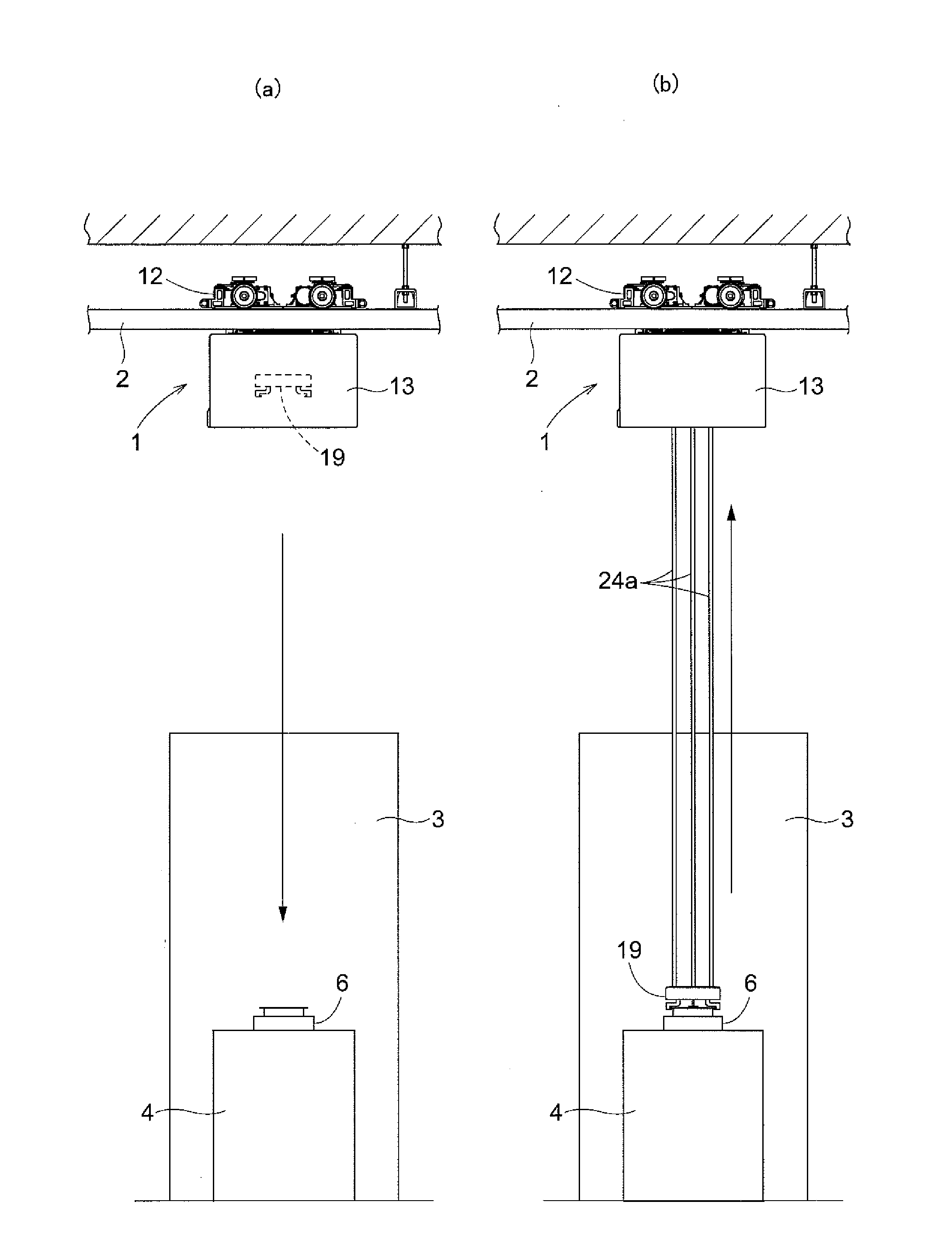
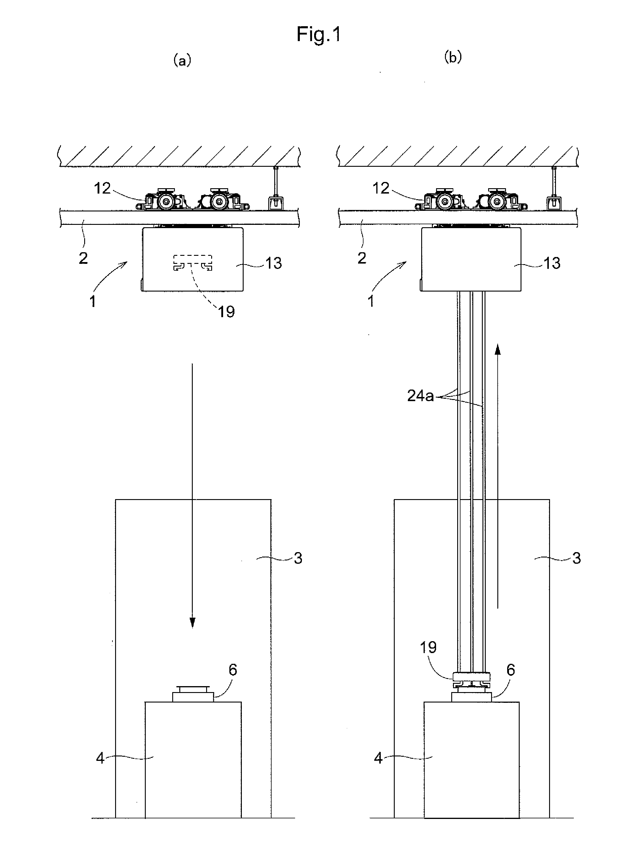
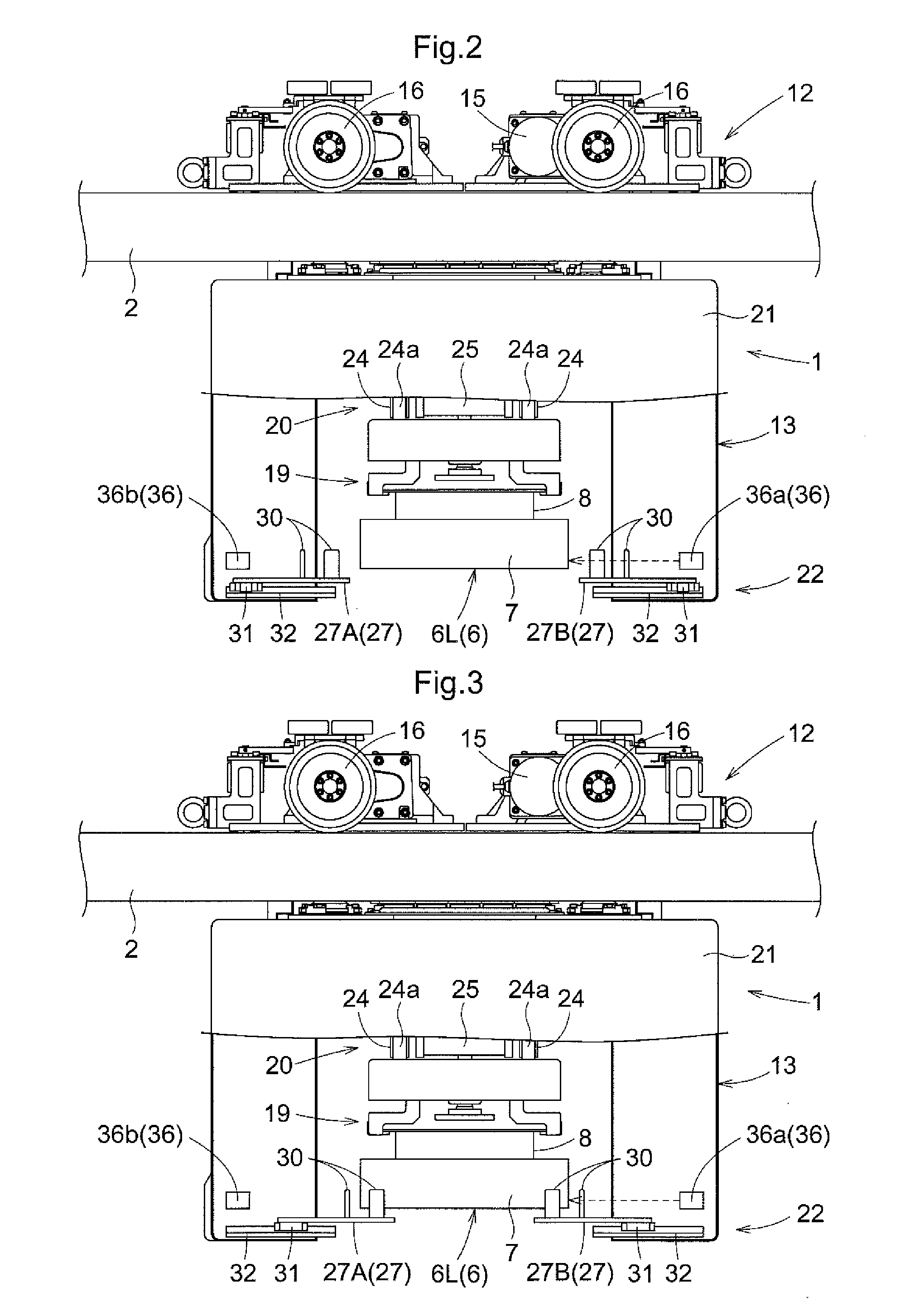
[0039]As shown in FIGS. 1-4, the article transport facility includes a ceiling, or overhead, transport vehicle 1 which functions as a transport device which can travel along a travel path while guided and supported by travel rails 2 provided along the travel path on the ceiling side, and a processing devices 3 each of which processes transported objects 6 or contents thereof. The ceiling transport vehicle 1 is configured to transport a transported object 6 transported from another location to a support platform 4 provided to each processing device 3, and is also configured to transport a transported object 6 on the support platform 4 to another location. Each processing device 3 is configured to transport the transported object 6 between the top of the support platform 4 and inside of the processing device 3 b...


PUM


Abstract

The distance between a pair of fall prevention members can be adjusted by causing the pair of fall prevention members to be linearly moved in mutually opposite directions along the spaced-apart direction along which the pair of fall prevention members are spaced apart from each other. A distance adjustment actuator portion is configured to be able to adjust the distance between the pair of fall prevention members to any of a distance for retraction greater than a width of a larger transported object in the spaced-apart direction; a distance for the larger transported object which is less than the distance for retraction and which corresponds to the width of the larger transported object in the spaced-apart direction; and a distance for the smaller transported object which is less than the distance for the larger transported object and which corresponds to a width of the smaller transported object in the spaced-apart direction.

Description

CROSS-REFERENCE TO RELATED APPLICATION[0001]This application claims priority to Japanese Patent Application No. 2014-003554 filed Jan. 10, 2014, which is hereby incorporated by reference in its entirety.FIELD OF THE INVENTION[0002]The present invention relates to a transport device comprising a support for suspending and supporting a transported object, a vertically moving portion for vertically moving the support to vertically move the transported object, that is suspended and supported by the support, between a transport position and a transfer position which is lower than the transport position, a pair of fall prevention members spaced apart from each other horizontally at locations below the transported object in the transport position, a distance adjustment actuator portion for adjusting a distance between the pair of fall prevention members in a spaced-apart direction along which the pair of fall prevention members are spaced apart from each other, and a movable member for sup...

Claims


Application Information

Patent Timeline
Patent Type & Authority Applications(United States)
IPC IPC(8): B66C19/00B66C13/18B66C13/06
CPCB66C19/00B66C13/18B66C13/06B66C1/28H01L21/67733B65G1/0457B65G35/00
Inventor TOMIDA, DAICHI
Owner DAIFUKU CO LTD
Why Eureka
Try Eureka