Method of manufacturing advanced features in a core for casting

a technology of advanced features and cores, which is applied in the direction of manufacturing tools, foundry patterns, foundry moulding apparatus, etc., can solve the problems of high cost of ceramic molds, excessive flash on fired parts, and a significant proportion of overall core cos

Active Publication Date: 2019-01-31
SIEMENS ENERGY GLOBAL GMBH & CO KG +1
View PDF2 Cites 31 Cited by
  • Summary
  • Abstract
  • Description
  • Claims
  • Application Information

AI Technical Summary

Benefits of technology

[0012]In another aspect of the present invention, a method of manufacturing advanced features in a ceramic core for a casting process comprises the steps of: providing a hard tool configuration comprising a first platform and a second platform, each having a center facing side; removably attaching a first end of a plurality of removable rake elements to the center facing side of the first platform and/or the second platform, wherein the plurality of removable rake elements comprise the first end and a second end; placing the center facing side of the first platform facing the center facin...

Problems solved by technology

This process leads to excessive flash on the fired part which requires substantial clean up (de-flash) and represents a significant proportion of overall core cost.
Ceramic molds are often difficult to produce and subject to distortion, breakage and low yields because the green body strength of the dried but unfired ceramic slurry is low, and it remains unsupported on its interior surface once the wax preform melts.
Misal...

Method used


Image

  • Method of manufacturing advanced features in a core for casting
  • Method of manufacturing advanced features in a core for casting
  • Method of manufacturing advanced features in a core for casting

Examples


Embodiment Construction

[0024]In the following detailed description of the preferred embodiment, reference is made to the accompanying drawings that form a part hereof, and in which is shown by way of illustration, and not by way of limitation, a specific embodiment in which the invention may be practiced. It is to be understood that other embodiments may be utilized and that changes may be made without departing from the spirit and scope of the present invention.

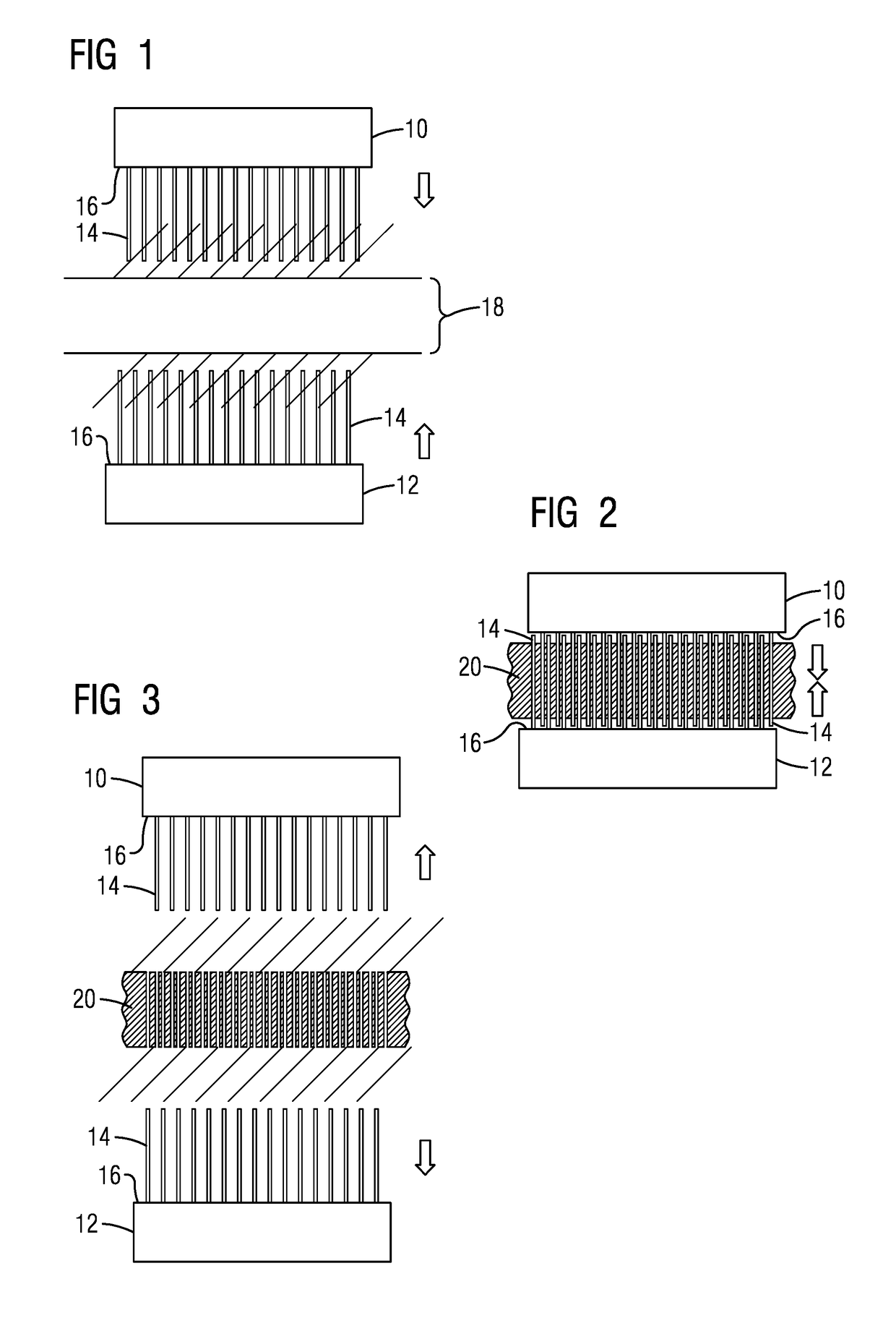
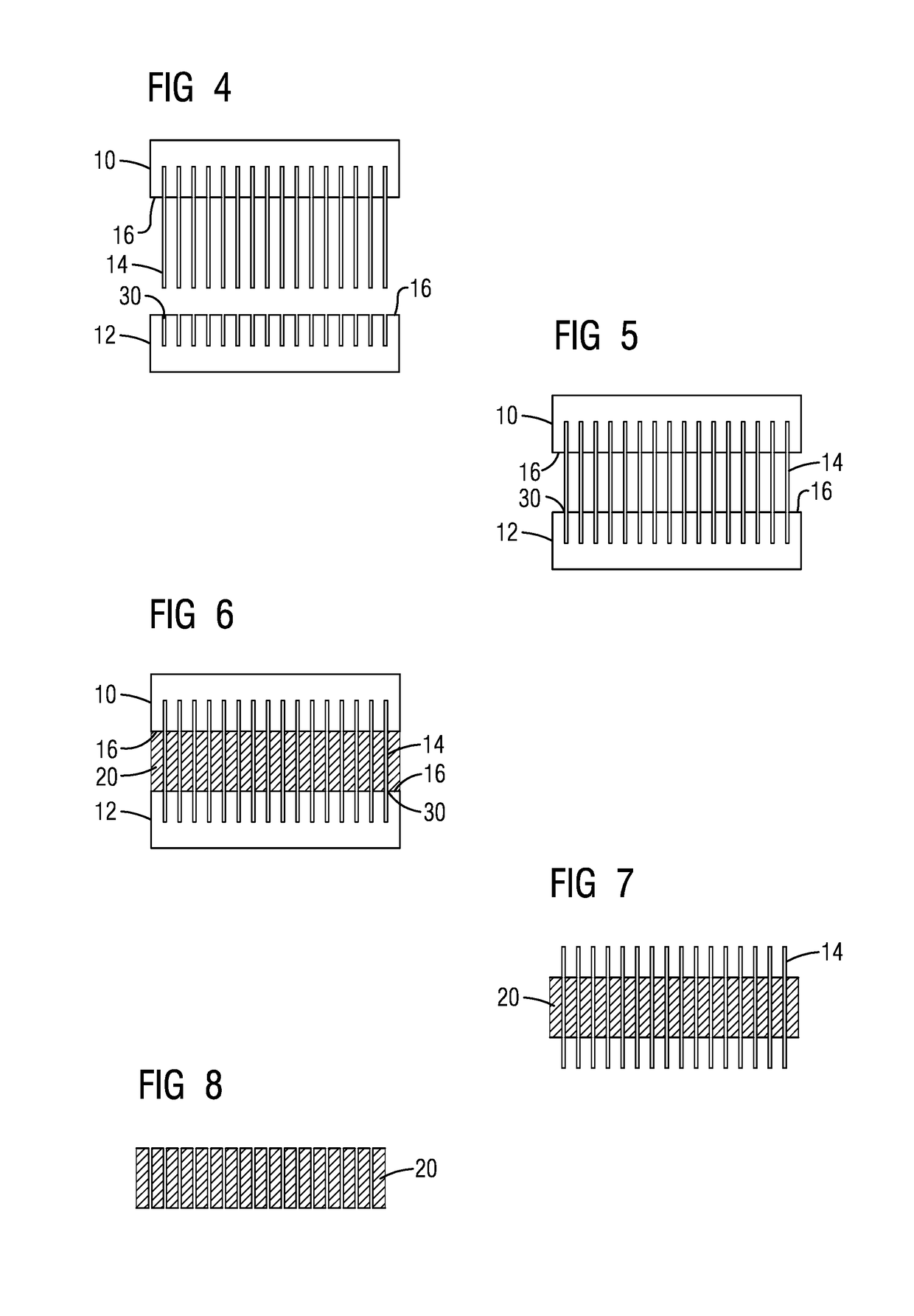
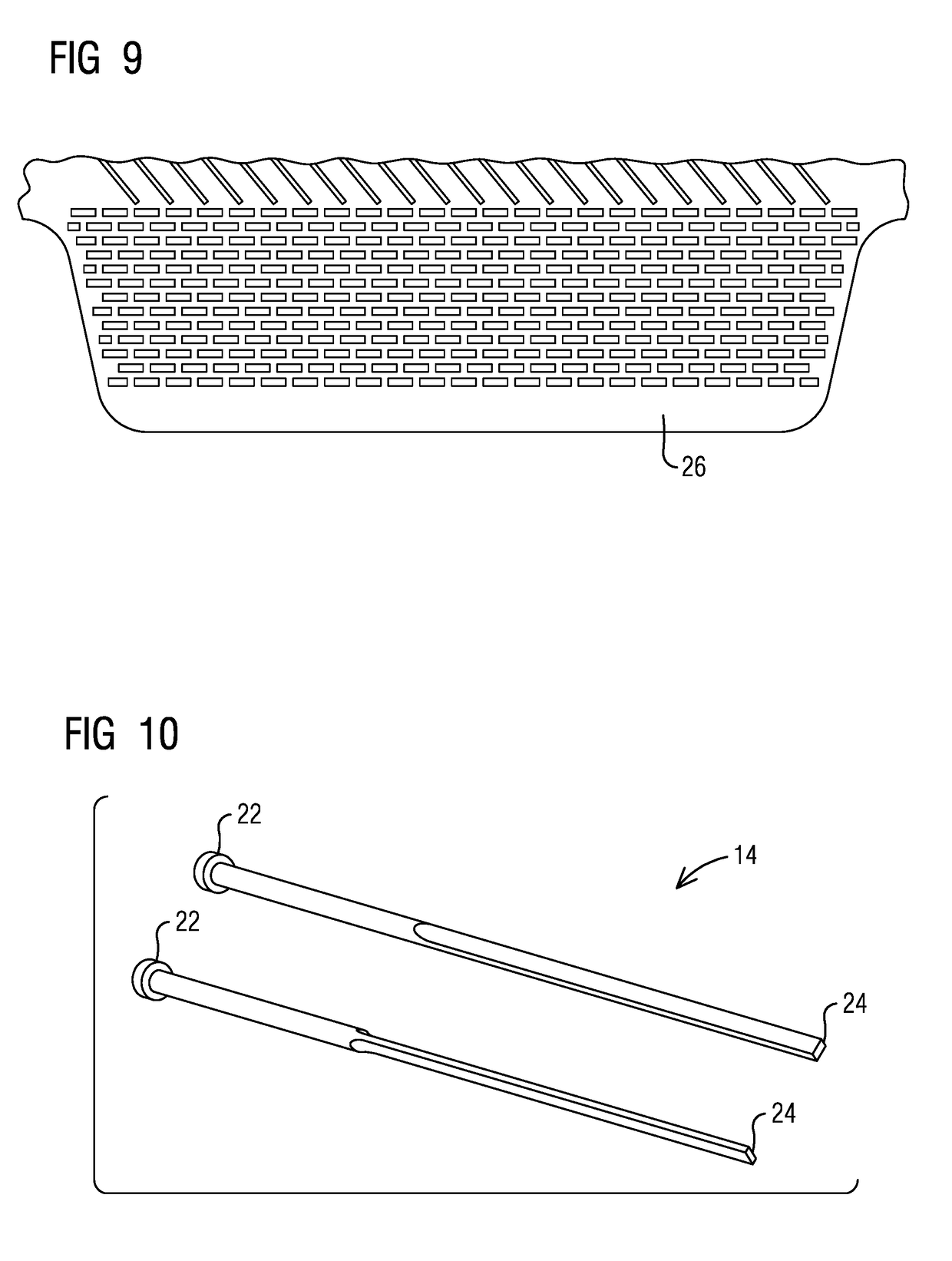
[0025]Broadly, an embodiment of the present invention provides a hard tool configuration and method of manufacturing advanced detailed trailing edge features in a core for casting. The hard tool configuration includes at least a first platform and a second platform. The hard tool configuration also includes a first end of a plurality of removable rake elements removably attached to at least one of the first platform and the second platform. The hard tool configuration also includes an internal mold geometry in a spacing in between the center facin...


PUM


Abstract

A hard tool configuration (28) and method of manufacturing advanced detailed trailing edge features in a core for casting. The hard tool configuration (28) includes at least a first platform (10) and a second platform (12). The hard tool configuration (28) also includes a first end (22) of a plurality of removable rake elements (14) removably attached to at least one of the first platform (10) and the second platform (12). The hard tool configuration (28) also includes an internal mold geometry (18) in a spacing in between the center facing side (16) of the first platform (10) and the center facing side (16) of the second platform (12).

Description

BACKGROUND1. Field[0001]The present invention relates to a method of manufacturing advanced features in a core for casting.2. Description of the Related Art[0002]In gas turbine engines, compressed air discharged from a compressor section and fuel introduced from a source of fuel are mixed together and burned in a combustion section, creating combustion products defining a high temperature working gas. The working gas is directed through a hot gas path in a turbine section of the engine, where the working gas expands to provide rotation of a turbine rotor. The turbine rotor may be linked to an electric generator, wherein the rotation of the turbine rotor can be used to produce electricity in the generator.[0003]In view of high pressure ratios and high engine firing temperatures implemented in modern engines, certain components, such as airfoils, e.g., stationary vanes and rotating blades within the turbine section, must be cooled with cooling fluid, such as air discharged from a comp...

Claims


Application Information

Patent Timeline
IPC IPC(8): B22C9/10B22C9/24B22C23/00
CPCB22C9/10B22C9/24B22C23/00F01D5/187F05D2230/21
Inventor MERRILL, GARY B.EAKINS, ROY
Owner SIEMENS ENERGY GLOBAL GMBH & CO KG
Why Eureka
Try Eureka