Permanent Magnet Electric Motor

Inactive Publication Date: 2019-01-31
JING JIN ELECTRIC TECHNOLOGIES (BEIJING) CO LTD
View PDF4 Cites 1 Cited by
  • Summary
  • Abstract
  • Description
  • Claims
  • Application Information

AI Technical Summary

Benefits of technology

The present patent is for a type of electric motor that uses a permanent magnet. The motor has a stator with evenly spaced teeth wound by coils. The size of the motor is limited by the number of magnetic poles, which can improve its speed of operation and safety. The stator is made from thin sheets made of a special material that has low power loss when in an alternating magnetic field, making the motor more efficient.

Problems solved by technology

However, the magnetic conductive materials of the stators generally have power loss in an alternating magnetic field, and the numerical value of the power loss when silicon steel sheets serve as the magnetic conductive material is very large.
Especially at the high speed operating range, the power loss even exceeds a half of the sum of the electric motor power loss, which results in a relatively low efficiency of the electric motor, and affects the operation safety.
Due to the small pole numbers, the widths of the magnets under each of the magnetic poles of the rotor are relatively large, and thus large centrifugal forces are generated, which is adverse to the high speed operation of the electric motors.

Method used


Image

  • Permanent Magnet Electric Motor

Examples


Embodiment Construction

[0015]The exemplary embodiments of the present disclosure will be described in further detail below by referring to the drawing. Although the drawing illustrates the exemplary embodiments of the present disclosure, it should be understood that, the present disclosure can be implemented in various forms, which should not be limited by the embodiments illustrated herein. In contrast, the purpose of providing those embodiments is to clearer understand the present disclosure, and to completely convey the scope of the present disclosure to a person skilled in the art.

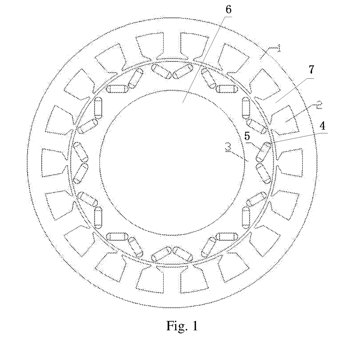
[0016]As shown in FIG. 1, the embodiment of the present disclosure provides a permanent magnet electric motor, which is a radial flux electric motor, consisting of a stator1, a rotor 3 and a rotating shaft 6. The rotor 3 is installed on the rotating shaft 6, and can drive the rotating shaft 6 to rotate. An inner circle of the stator 1 is provided with N stator slots evenly in circumferential direction, wherein, the N is an i...


PUM


Abstract

The present disclosure discloses a permanent magnet electric motor, which is a radial flux electric motor, consisting of a stator and a rotor, wherein an inner circle of the stator is provided with N stator teeth evenly in circumferential direction, each of the stator teeth is wound by a coil, and the N coils form stator windings, wherein, the N is an integer not less than 12. Additionally, the number of magnetic poles of the rotor is not less than 12 so that widths and the centrifugal forces of the magnets under each of the magnetic poles are limited, thereby facilitating the high speed operation of the electric motor and improving the safety. The stator is manufactured by laminating a plurality of annular thin sheets with a same shape, and the material of the annular thin sheets is an amorphous magnetic conductive material, whose power loss in an alternating magnetic field is lower than that of silicon steel, which hugely increases the efficiency of the electric motor.

Description

TECHNICAL FIELD The present disclosure relates to the field of electric motors, and in particular to a permanent magnet electric motor.BACKGROUND ART[0001]The presently commonly known structure of the electric motors used for vehicles consists of a stator, a rotor, a rotating shaft, a machine base, etc. The stator is generally manufactured by laminating cold rolled silicon steel sheets with preformed slots, and installing windings into the slots. However, the magnetic conductive materials of the stators generally have power loss in an alternating magnetic field, and the numerical value of the power loss when silicon steel sheets serve as the magnetic conductive material is very large. Especially at the high speed operating range, the power loss even exceeds a half of the sum of the electric motor power loss, which results in a relatively low efficiency of the electric motor, and affects the operation safety. The electric motors with the traditional structures, in order to reduce the...

Claims


Application Information

Patent Timeline
IPC IPC(8): H02K21/16H02K1/02H02K1/14H02K1/27
CPCH02K21/16H02K1/02H02K1/146H02K1/276H02K2213/03H02K1/145H02K1/274H02K21/14H02K1/16
Inventor ZHANG, LIANGLIANGZHANG, PEI
Owner JING JIN ELECTRIC TECHNOLOGIES (BEIJING) CO LTD
Why Eureka
Try Eureka