Motor vehicle headlamp assembly

Active Publication Date: 2019-02-07
AUTOMOTIVE LIGHTING REUTLINGEN GMBH
View PDF0 Cites 2 Cited by
  • Summary
  • Abstract
  • Description
  • Claims
  • Application Information

AI Technical Summary

Benefits of technology

[0006]Based on the prior art described above, the fundamental object of the invention is to create and further develop a motor vehicle headlamp of the type specified in the introduc

Problems solved by technology

One problem with known LiDAR systems is that the backscattering cross section from illuminated objects in the center in front of the motor vehicle is significantly larger than fr

Method used


Image

  • Motor vehicle headlamp assembly
  • Motor vehicle headlamp assembly
  • Motor vehicle headlamp assembly

Examples


Example

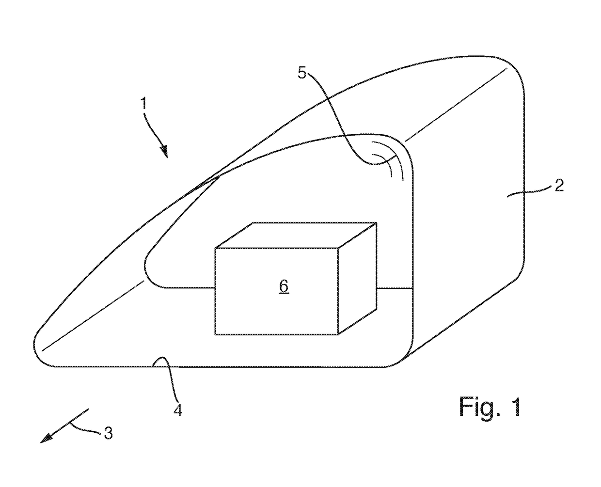
[0036]The present invention relates to a motor vehicle headlamp assembly that has at least one motor vehicle headlamp 1, as shown by way of example in FIG. 1. The headlamp 1 is disposed at an arbitrary location on the outside of a motor vehicle, preferably in a suitable installation opening in the front region of a motor vehicle. The motor vehicle preferably comprises two headlamps 1 disposed at a spacing to one another in the front region thereof, in particular a right-hand headlamp and a left-hand headlamp. The headlamp 1 generates predefined light distributions. The light distributions can fulfill arbitrary headlamp functions, e.g. low beams, high beams, fog lights and / or arbitrary adaptive light distributions (e.g. partial high beams).

[0037]The headlamp 1 comprises a housing 2, preferably made of a transparent material, in particular plastic. The housing 2 has a light emission opening 4 oriented in the direction of the light emission 3, which is closed by a cover plate 5. The co...


PUM


Abstract

A headlamp assembly for a motor vehicle comprising at least one headlamp, which has a light source for emitting visible light, a radiation source for emitting infrared radiation, and a light emission optics with a light entry surface, which visible light from the light source and infrared radiation from the radiation source strikes, and which has an optical exit-deflection element, which directs the infrared radiation from the radiation source toward the light entry surface of the light emission optics. The optical exit-deflection element comprises at least one optics, which broadens the infrared radiation emitted by the radiation source to form a radiation beam with a cross section broadened in a horizontal plane (HH), and a radiation distribution that has at least one intensity maximum disposed toward the edge in the radiation distribution, to one side of a vertical plane (VV), when viewed in a focal plane of the light emission optics.

Description

CROSS-REFERENCE TO RELATED APPLICATIONS[0001]The present claims priority to and all the benefits of German Patent Application No. 10 2017 117 591.1, filed on Aug. 3, 2017, which is hereby expressly incorporated herein by reference in its entirety.BACKGROUND OF THE INVENTION1. Field of the Invention[0002]The present invention relates to a motor vehicle headlamp assembly comprising at least one headlamp. The at least one headlamp has a light source for emitting visible light, at least one radiation source for emitting infrared radiation, and a light emission optics that has a light entry surface. Visible light from the light source and invisible infrared radiation from the at least one radiation source strike the light entry surface of the light emission optics. Furthermore, the at least one headlamp has at least one optical exit-deflection element, which directs the infrared radiation emitted by the at least one radiation source to the light entry surface of the light emission optics...

Claims


Application Information

Patent Timeline
IPC IPC(8): B60Q1/00G01S17/93G01S17/931
CPCB60Q1/0023G01S17/936G01S17/42G01S7/481F21S41/16F21S41/13F21S41/18G01S2013/93277G01S17/931F21S41/00
Inventor LICHT, MARTINBUCHBERGER, CHRISTIANKNITTEL, JOACHIM
Owner AUTOMOTIVE LIGHTING REUTLINGEN GMBH
Why Eureka
Try Eureka