
A blast-retaining panel wall and connectors thereof

Inactive Publication Date: 2019-02-07
BD SYST EURO LTD
View PDF18 Cites 0 Cited by
  • Summary
  • Abstract
  • Description
  • Claims
  • Application Information

AI Technical Summary

Benefits of technology

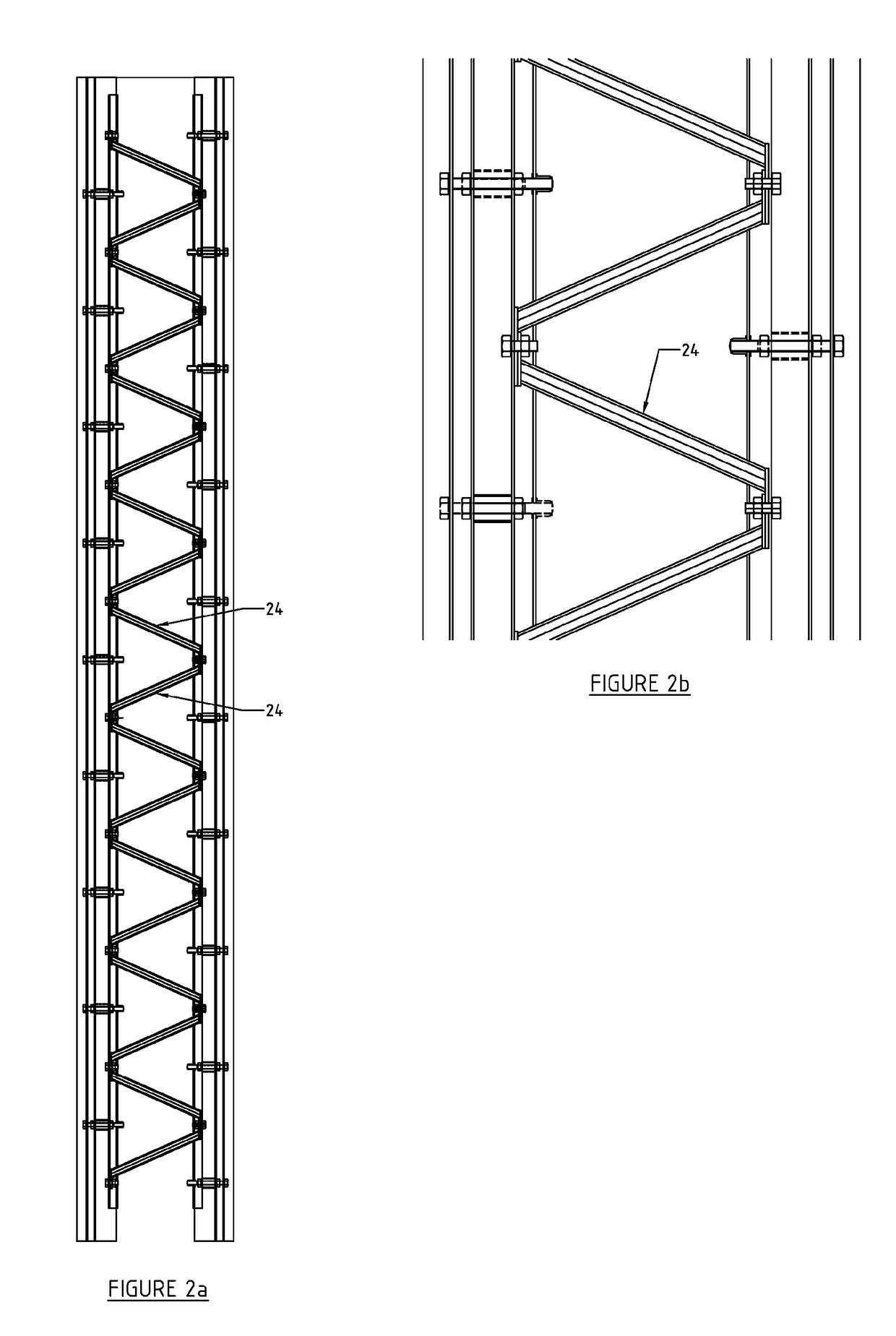
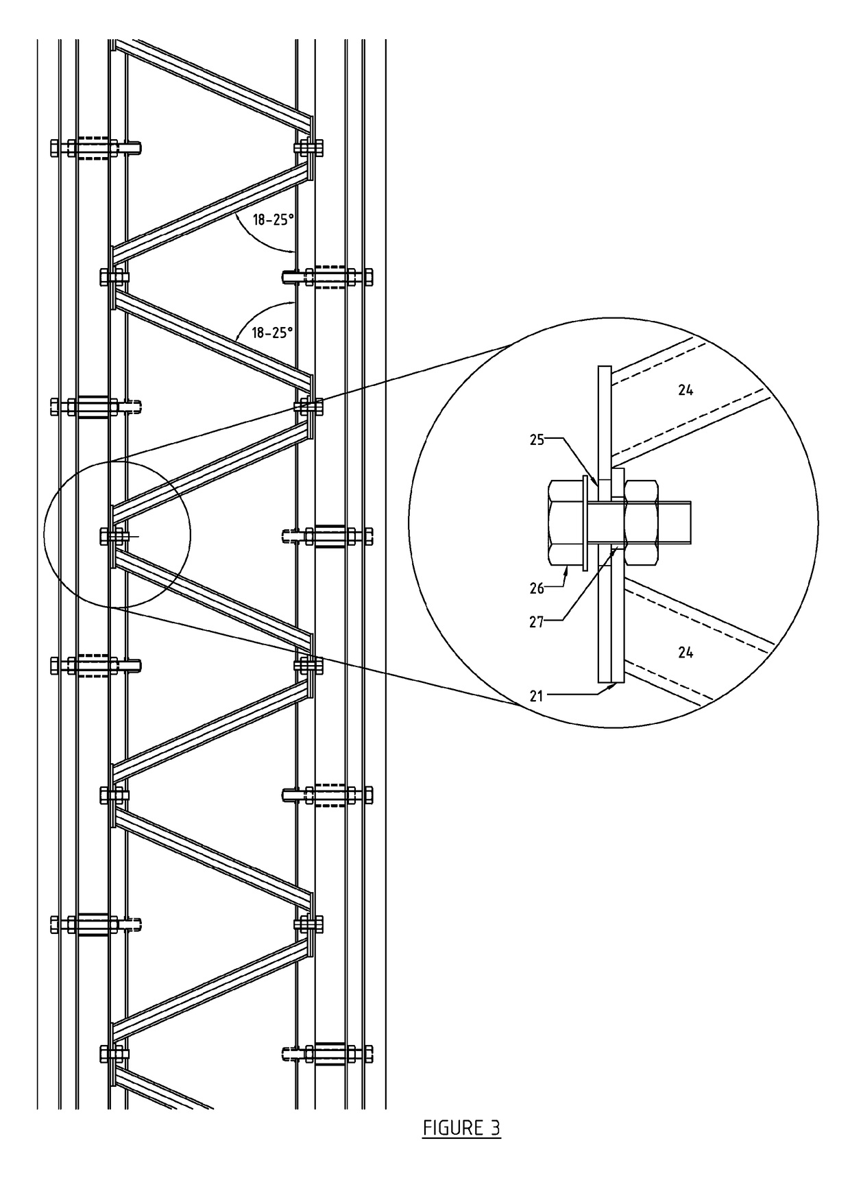
The patent describes a new design for panels used in protective structures against blast and fire. The design includes a cell wall with a cover that improves heat dissipation. The panels are reinforced to withstand explosive blast and further explosions. The panels can be easily assembled and have a solid, integral structure. The cover has a configuration that prevents heat from penetrating the joints between the panels. The cover is secured to the panels to strengthen the joint and minimize disruption and weakening of the panels. The design utilizes angled lattice members that allow the structure to bend or crumple.

Problems solved by technology

A difficulty in constructing such a wall is that in order to prevent a shockwave from an explosion from passing through the wall, the wall often needs to be made of strong materials which are typically, relatively dense materials.
As such, the walls produced can be heavy, which is an obvious disadvantage, for example on transport and installation, but also problematic where the wall is to be installed into a floating structure such as a boat or an oil rig.
One disadvantage of the wall and assembly disclosed therein is that although the joint can absorb energy, the single wall layer needs to be able to withstand the forces purely by means of its internal structure and material strength.
This wall, disclosed in GB2277943 is primarily a firewall and if subjected to a blast which is beyond a certain limit, the force of the blast will cause the connected panels to separate and thereby causing the blast retaining wall to fail.

Method used


Image

  • A blast-retaining panel wall and connectors thereof
  • A blast-retaining panel wall and connectors thereof
  • A blast-retaining panel wall and connectors thereof

Examples


Embodiment Construction

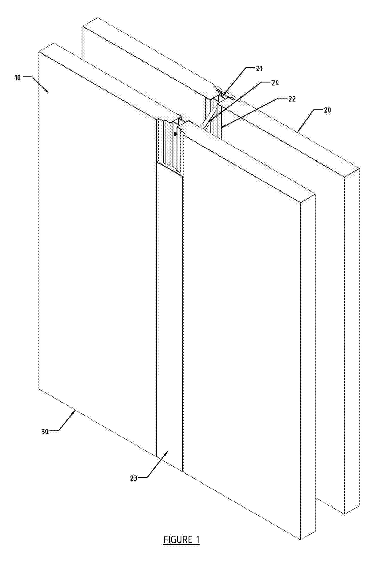
[0033]The invention herein described relates to a series of panels, assembled together in edge-to-edge configuration to form a barrier wall to contain an explosion and / or fire from one side of the wall. Due to the modular nature of the wall, this can be installed relatively quickly when required and also subsequently removed relatively quickly if the need for the wall ends or changes, or to replace a particular panel. The walls contemplated can have a single layer of panels or, in a preferred embodiment, a plurality of layers with two layers being especially preferred. One standard which needs to be met relates to heat transfer which must be sufficiently low that where the temperature on one side of the wall is high, for example of the order of 1500°C., the temperature on the other side of the wall remains below 180°C., which is well below the auto-ignition temperature of many materials such as paper.

[0034]The nature of the assembly means provides for a continuous barrier, including...


PUM


Abstract

A blast-resistant wall (10) comprises a first panel (20) and a second panel (30) in face-to-face spaced parallel arrangement is disclosed and securing means (21, 22) to secure the said panels (20, 30), in spaced end-to-end relationship with a further first panel and a second panel respectively, forming a first and second panel assemblies. To secure said panel-engaging portion to a panel, the securing means (21, 22) comprises a panel engaging portion (55) engaging a face (56) of each of neighbouring first or second panels (20, 30), A spacer section (52) separates the ends of adjacent panels. The first and second panel assemblies are connected via a plurality of lattice members (24), each lattice member (24) is attached at a first end to securing means engaging a first panel and at a second end to securing means engaging a second panel and extending between the panels, A cover member (70) bridges across adjacent first panels and second panels on the outer faces of the first panels and second panels and covers the spacer section.

Description

FIELD OF THE INVENTION[0001]The present invention relates to a blast-retaining wall comprising a plurality of connected panels and also two connectors to connect said panels. The invention additionally relates to a wall comprising two sets of connecting panels and spaced in parallel relationship. The invention further relates to a means of connecting wall panels together.BACKGROUND TO THE INVENTION[0002]Known walls are retrofitted onto existing offshore jacket installations and in use, protect personnel and equipment from a fire, explosion or combination thereof is well-known in the art. Such walls need not only to be able to withstand the shockwave which is generated by the explosion, but also to withstand the heat generated both over the short term, but also possibly over a longer term as a resulting fire continues to burn.[0003]Many types of wall are known in the art. A difficulty in constructing such a wall is that in order to prevent a shockwave from an explosion from passing t...

Claims


Application Information

Patent Timeline
IPC IPC(8): E04B1/98
CPCE04B1/98E04B2/62E04B2/8652F41H5/24E04H9/06
Inventor LEPPARD, IAN
Owner BD SYST EURO LTD
Learn More