Air conditioning blower hole apparatus

a blower and hole technology, applied in the field of air conditioning blower hole apparatus, can solve the problems of difficult to maintain the second fin at a desired position in the more air-volume mode, the diameter cannot be easily determined, and the inevitably large diameter becomes large, so as to facilitate assembly, reduce the interference between the retainer and the small-diameter hole, and reduce the deformation of the small-diameter hole

Inactive Publication Date: 2019-02-14
MORIROKU TECH
View PDF5 Cites 5 Cited by
  • Summary
  • Abstract
  • Description
  • Claims
  • Application Information

AI Technical Summary

Benefits of technology

[0065]An interference between the retainer part and the small-diameter hole is minimized when the link is assembled. Consequently, a deformation of the small-diameter hole is suppressed, and the assembling is facilitated.
[0066]Moreover, since the shape that decreases the diameter toward the tip achieves a guiding action, facilitating the retainer part to enter the small-diameter hole, thereby suppressing a deformation of the small-diameter hole and improving an assembling easiness.
[0067]According to the fifth embodiment of the present disclosure, the link includes the link body, and the cylindrical boss partially provided on the link body. Since the portion between the adjacent bosses can be thinned, achieving a weight saving of the link, and a reduction of the necessary amount of a resin material.

Problems solved by technology

However, the action enlarged by the head part remains, and thus the diameter inevitably becomes large.
In a more air-volume mode, the air volume increases. when the sliding friction is small, it is difficult to maintain the second fin at a desired position in the more air-volume mode.
However, when the diameter of the second engagement hole is reduced beforehand, such a diameter cannot be decided easily.
Hence, when the diameter is reduced beforehand as described above, the number of designing steps increases, resulting in a cost increase.
Although the head part of the second fin may be eliminated, it is difficult to prevent the fin from being detached from the coupling member when there is no head part.
Since the gap is wide, the second fin may be loosen by such a gap, and thus it is difficult to maintain the second fin at the intended position against the air volume in the more air-volume mode.
Rotation of the fin makes the assembling work laborious.
Moreover, as for the rotatable angle of the fin, although a sufficient actuation range is secured as the actuation range in a normal use, the fin is not able to rotate largely when, for example, the fin is fully closed.
This decreases the flexibility in designing.
Adoption of another component increases the costs.
That is, although JP 2006-015840 A can address the looseness of the fin, the structure is complicated which is likely to increase the costs.

Method used


Image

  • Air conditioning blower hole apparatus
  • Air conditioning blower hole apparatus
  • Air conditioning blower hole apparatus

Examples


embodiment

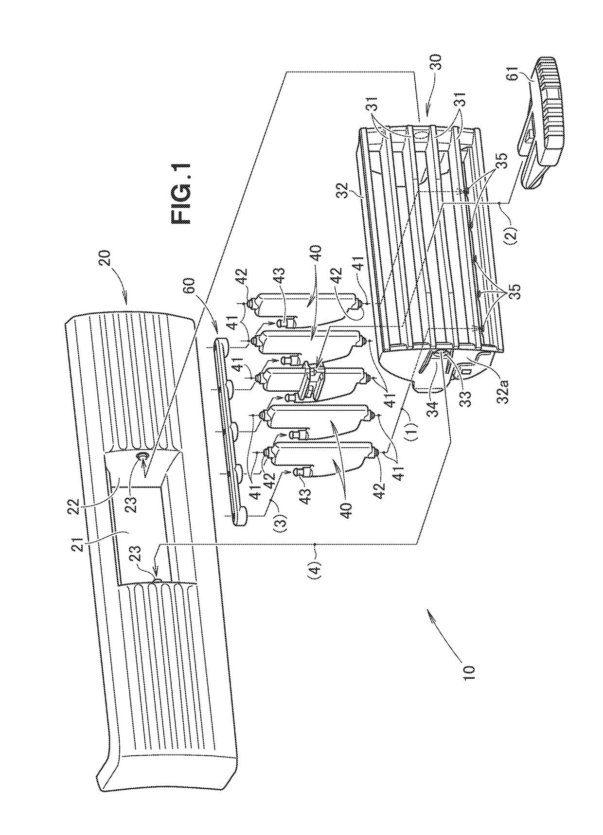
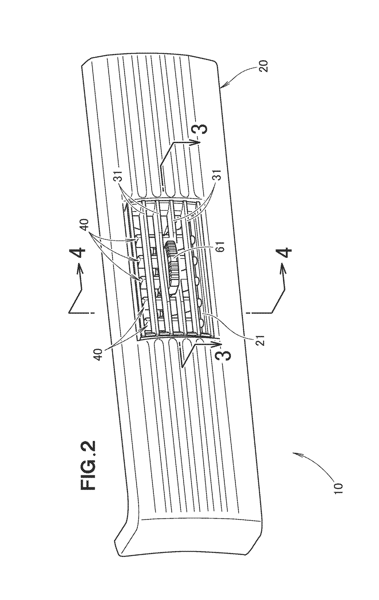
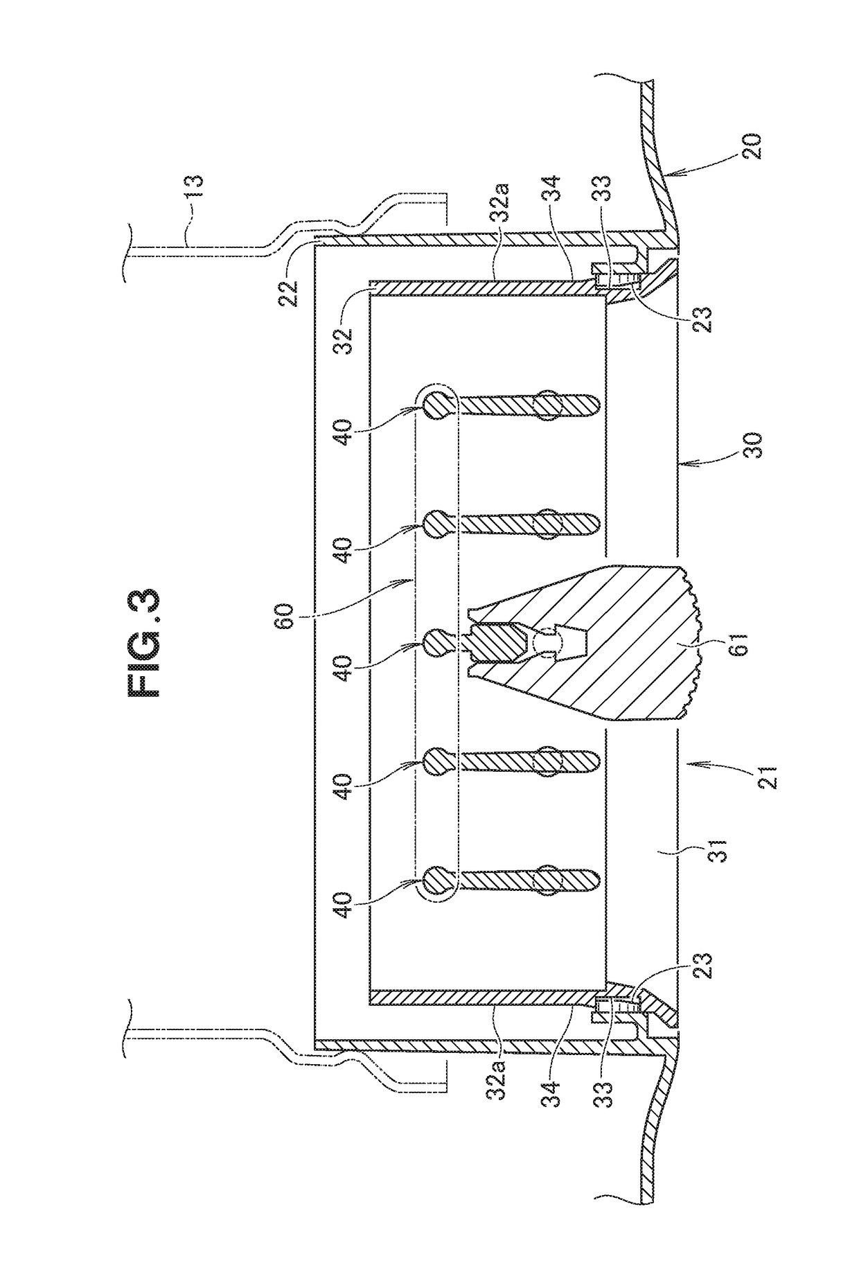
[0083]As illustrated in FIG. 1, an air conditioning blower hole apparatus 10 includes a blower hole panel 20 that has a blower hole 21 formed in the front (a surface toward the interior of a vehicle), a fin assembly 30 that has plurality of horizontal fins 31 arranged in parallel with each other, plurality of fins 40 attached to this fin assembly 30, a link 60 that couples these fins 40, and an operation knob 61 attached to one of the plurality of fins 40.

[0084]The fins 40 are placed behind the horizontal fins 31 (a distal side from the interior of the vehicle), and is placed vertically so as to be substantially orthogonal to the horizontal fins 31.

[0085]The fins 40 are attached to the fin assembly 30 so as to be rotatable around respective axial lines 41 in parallel with each other.

[0086]The link 60 extends in the direction in which the plurality of fins 40 are placed. The fins 40 are rotatable relative to the link 60.

[0087]The blower hole panel 20 has a rectangular cylindrical par...


PUM


Abstract

An air conditioning blower hole apparatus is provided which is capable of suppressing a looseness of a fin, and of decreasing production costs. This air conditioning blower hole apparatus includes: a plurality of fins; and a link coupled with the plurality of fins. At least one fin includes: a fin body; a large-diameter shaft part extending from the fin body; a small-diameter shaft part extending from the large-diameter shaft part, and having a smaller diameter than a diameter of the large-diameter shaft part; and a retainer part provided at a tip of the small-diameter shaft part, and having a larger diameter than the small-diameter shaft part. The link is provided with a large-diameter hole corresponding to the large-diameter shaft part and a small-diameter hole corresponding to the small-diameter shaft part. A gap is secured between the small-diameter shaft part and the small-diameter hole.

Description

FIELD OF THE INVENTION[0001]The present disclosure relates to a fin apparatus provided at a blower hole of an automobile or vehicular air conditioning device.[0002]In particular, the present disclosure relates to a blower hole apparatus which has plurality of fins provided in parallel with each other within a ventilation channel, and which adjusts the direction of blown air by rotating the fins.BACKGROUND[0003]In this specification, the term “contact-slide” means when a member moves relative to another member, the member moves along a contact surface with the member being in contact with another member.[0004]JP H08-113029 A and JP 2006-015840 A disclose an air conditioning blower hole apparatus for an automobile.[0005]According to JP H08-113029 A, the plurality of fins include at least one first fin, and a remaining second fin.[0006]A coupling shaft of the second fin is formed in a shape that includes a cylindrical shaft part and a circular head part with a larger dimension than tha...

Claims


Application Information

Patent Timeline
Patent Type & Authority Applications(United States)
IPC IPC(8): B60H1/34F24F13/15
CPCB60H1/3428F24F13/15B60H2001/3464B60H2001/3471B60H2001/3492B60H1/34
Inventor TANAKA, TAKASHIFUKUDA, YUSUKE
Owner MORIROKU TECH
Why Eureka
Try Eureka