Hydraulic control device

a control device and hydraulic technology, applied in the direction of machines/engines, positive displacement liquid engines, servomotors, etc., can solve the problems of repeated opening and closing of check valves, variation of so as to avoid deterioration of fuel efficiency of vehicles, suppress variation in oil pressure to be supplied to the hydraulic operation unit, and avoid hunting of check valves

Active Publication Date: 2019-02-14
HONDA MOTOR CO LTD
View PDF0 Cites 1 Cited by
  • Summary
  • Abstract
  • Description
  • Claims
  • Application Information

AI Technical Summary

Benefits of technology

[0010]If the request output is beyond the discharging capability, the second pump is stopped or the rotation number is decreased; therefore, the oil can be supplied to the hydraulic operation unit as appropriate in accordance with the vehicle state. Thus, the deterioration in fuel efficiency of the vehicle can be avoided.
[0011]In addition, if the request output is beyond the discharging c...

Problems solved by technology

In such cases, if the second pump is continuously driven with the check valve open, the second pump does wasteful work, and as a result, the fuel efficiency of the vehicle deteriorates.
In addition, when the first pump and the second pump are operated t...

Method used


Image

  • Hydraulic control device
  • Hydraulic control device
  • Hydraulic control device

Examples


Embodiment Construction

[0027]A preferred embodiment of a hydraulic control device according to the present invention will hereinafter be described in detail with reference to the attached drawings.

1. Structure of the Present Embodiment

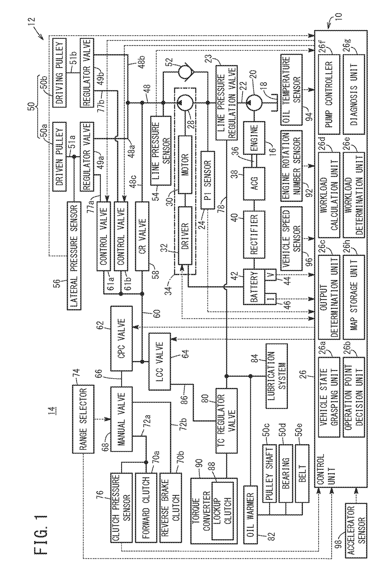
[0028]FIG. 1 is a structure diagram of a hydraulic control device 10 according to the present embodiment. The hydraulic control device 10 is used in, for example, a vehicle 14 including a transmission 12 corresponding to a continuously variable transmission (CVT).

[0029]The hydraulic control device 10 includes a first pump (mechanical pump) 20 that is driven by an engine 16 of the vehicle 14 and pumps up oil (hydraulic oil) stored in a reservoir 18 and transfers the oil with pressure. An output side of the first pump 20 is connected to an oil passage 22.

[0030]The oil that is transferred with pressure from the first pump 20 flows as first oil in the oil passage 22. In the middle of the oil passage 22, a line pressure regulation valve 23 corresponding to a spool valve is provid...


PUM


Abstract

In a control unit of a hydraulic control device, a vehicle state grasping unit grasps a vehicle state of a vehicle, and an output determination unit determines whether an operation point depending on the vehicle state that is decided by an operation point decision unit is over a discharging capability limit line. A pump controller stops a second pump or decreases a rotation number if the output determination unit determines that the operation point is over the discharging capability limit line.

Description

CROSS-REFERENCE TO RELATED APPLICATION[0001]This application is based upon and claims the benefit of priority from Japanese Patent Application No. 2017-155239 filed on Aug. 10, 2017, the contents of which are incorporated herein by reference.BACKGROUND OF THE INVENTIONField of the Invention[0002]The present invention relates to a hydraulic control device that has, between a first pump and a hydraulic operation unit, a second pump and a check valve connected in parallel, and that supplies first oil from the first pump to the hydraulic operation unit through the check valve, or pressurizes the first oil with the second pump and supplies the first oil that has been pressurized to the hydraulic operation unit as second oil.Description of the Related Art[0003]For example, Japanese Laid-Open Patent Publication No. 2015-200369 discloses a hydraulic control device in a transmission of a vehicle that has, between a first pump (mechanical pump) and a hydraulic operation unit of the transmissi...

Claims


Application Information

Patent Timeline
IPC IPC(8): F04B49/20F16H61/00F15B11/17F04B17/03F04B17/05F04B23/04
CPCF04B49/20F16H61/0031F15B11/17F04B17/03F04B17/05F04B23/04F16H59/72F15B2211/20576F15B2211/6651F16H61/662F16H61/664F15B11/165F04B49/02
Inventor HARADA, MASAMICHISAKAGAMI, KYOHEI
Owner HONDA MOTOR CO LTD
Why Eureka
Try Eureka