System and Method For Phase-Contrast MRI with Hybrid One-and Two-sided Flow Encoding and Velocity Spectrum Separation (HOTSPA)

a phase-contrast and flow encoding technology, applied in the field of system and method for phase-contrast mri with hybrid, can solve the problems of not always feasible to determine if a stenosis, not always accurate or sufficient, and the contrast agent that must be administered to enhance the blood vessel carries a significant financial cost, so as to reduce the temporal sampling period and temporal footprint, and sample the hybrid m1-t space more efficiently.

Active Publication Date: 2019-02-21
RGT UNIV OF CALIFORNIA
View PDF0 Cites 5 Cited by
  • Summary
  • Abstract
  • Description
  • Claims
  • Application Information

AI Technical Summary

Benefits of technology

The present patent describes an improved method called HOTSPA which solves problems with existing flow or velocity encoded magnetic resonance imaging (MRI). It uses a combination of single-side and double-side flow encodings during MRI scans. By measuring the speed at which blood flows through different parts of the body, this approach helps calculate the movement of fluid in real time without requiring multiple measurements. Overall, this technique makes it possible to get accurate results faster and with fewer resources compared to other flow MRI approaches.

Problems solved by technology

The technical problem addressed in this patent text is improving the timing and precision of phased contrast (PC)-based magnetic resonance angiography (MRA), while reducing the duration of the examination and minimizing the risk of harmful side effects caused by the injection of contrast agents. Current techniques involve either slowing down the rate at which new frames of data are collected or increasing the size of the resulting images, leading to potential issues with temporal resolution and footprint when trying to evaluate the maxpeak value of brain activity. Additionally, current systems tend to apply fixed bipolar gratients in only in specific ways that negatively impact the detection of flowing spins. To address these challenges, researchers have attempted to develop better tools like faster magnetic echo imaging and optimized scheduling of multiple sequences to improve the speed and accuracy of PC-related measures.

Method used


Image

  • System and Method For Phase-Contrast MRI with Hybrid One-and Two-sided Flow Encoding and Velocity Spectrum Separation (HOTSPA)
  • System and Method For Phase-Contrast MRI with Hybrid One-and Two-sided Flow Encoding and Velocity Spectrum Separation (HOTSPA)
  • System and Method For Phase-Contrast MRI with Hybrid One-and Two-sided Flow Encoding and Velocity Spectrum Separation (HOTSPA)

Examples


example

[0074]An example study was performed on a 3T scanner with a 4-channel neck (in vivo studies) coil. As used in this study, “mean flow velocity” means the average velocity within the entire blood vessel lumen. Also, “peak velocity” means the maximum velocity within the entire blood vessel. Further, “magnitude velocity” means the square root of sum of squares of 3D velocities (=√{square root over (Vx2+Vy2+Vz2)}). The magnitude mean flow velocity can be used to indicate the average magnitude velocity within the entire blood vessel lumen, and magnitude peak velocity can be used to indicate the maximum magnitude velocity within the entire blood vessel lumen. Finally, “maximum velocity” means the maximum velocity within the entire cardiac cycle. This often happens in the peak systolic cardiac phases.

Retrospective In Vivo Study (2D)

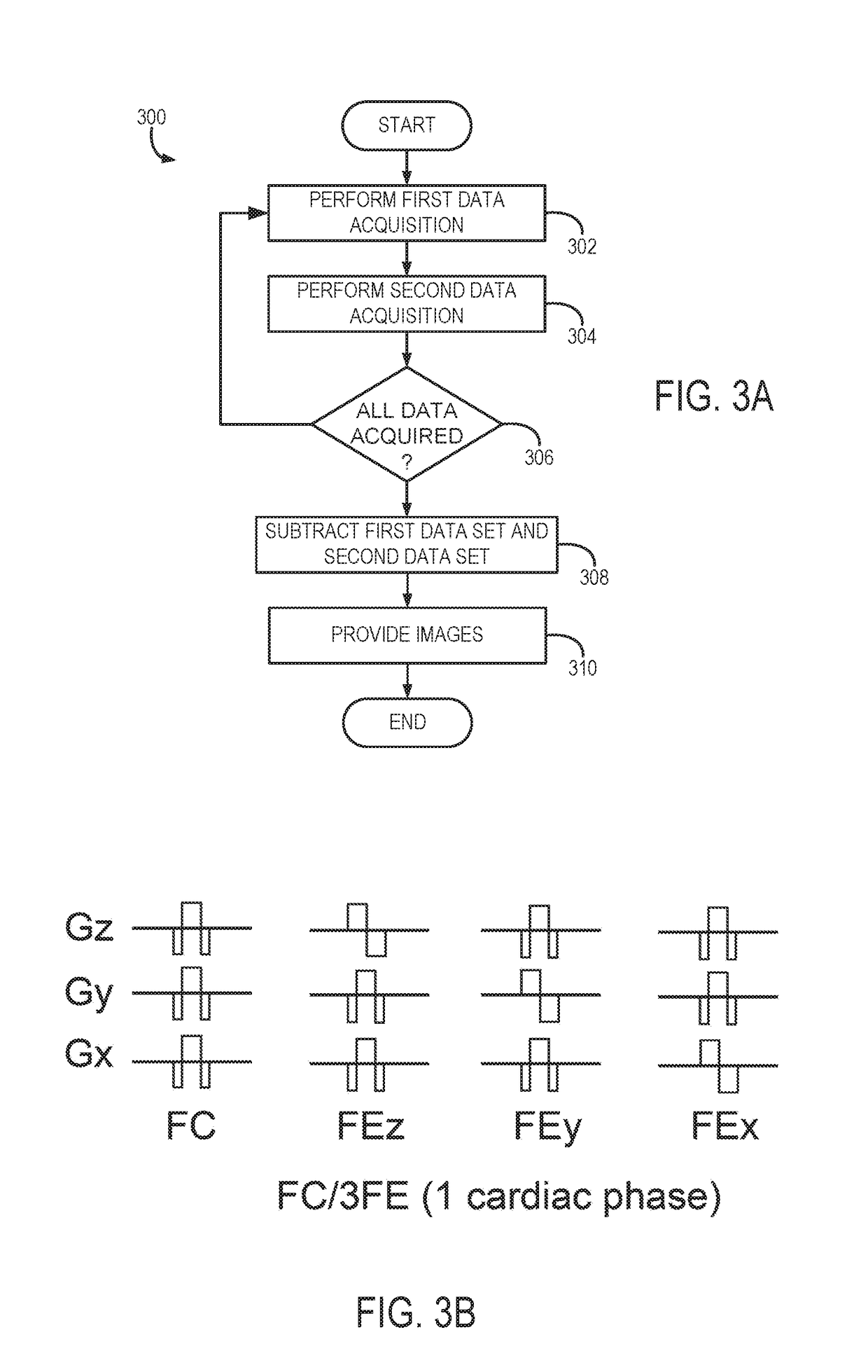
[0075]The commons carotid arteries (CCAs) of six volunteers were scanned using a 2D PC-MRI sequence with 3 FE directions (FC / 3FE). The sequence parameters includ...


PUM


Abstract

A system and method is provided for acquiring flow encoded data from a subject using a magnetic resonance imaging (MRI) system. The method includes acquiring flow encoded (FE) data with alternating encoding polarities and along two of three orthogonal directions through the subject over at least two cycles of the flow within the subject; and separating the FE data into directional FE datasets using a temporal filter that separates the FE data based on temporal modulation of the FE directions caused by the alternating encoding polarities extending over the at least two cycles of the flow within the subject that shift the Fourier spectrum of velocity waveforms corresponding to the FE data. The method also includes using the directional FE datasets to generate an image of the subject showing flow within the subject caused by the at least two cycles of flow within the subject.

Description


Claims


Application Information

Patent Timeline
Owner RGT UNIV OF CALIFORNIA
Why Eureka
Try Eureka