Modular rotary cutting tool

Active Publication Date: 2019-02-21
KENNAMETAL INC
View PDF5 Cites 2 Cited by
  • Summary
  • Abstract
  • Description
  • Claims
  • Application Information

AI Technical Summary

Benefits of technology

[0003]Embodiments of the invention are directed to addressing problems associated with excessive stresses and deformation of the pocket structure by providing clamping surfaces that are inclined with respect to the central, longitudinal axis

Problems solved by technology

Unfortunately, in these designs, the radial and axial forces that occur during a drilling operation, especially on uneven or inclined surfa

Method used


Image

  • Modular rotary cutting tool
  • Modular rotary cutting tool
  • Modular rotary cutting tool

Examples


Embodiment Construction

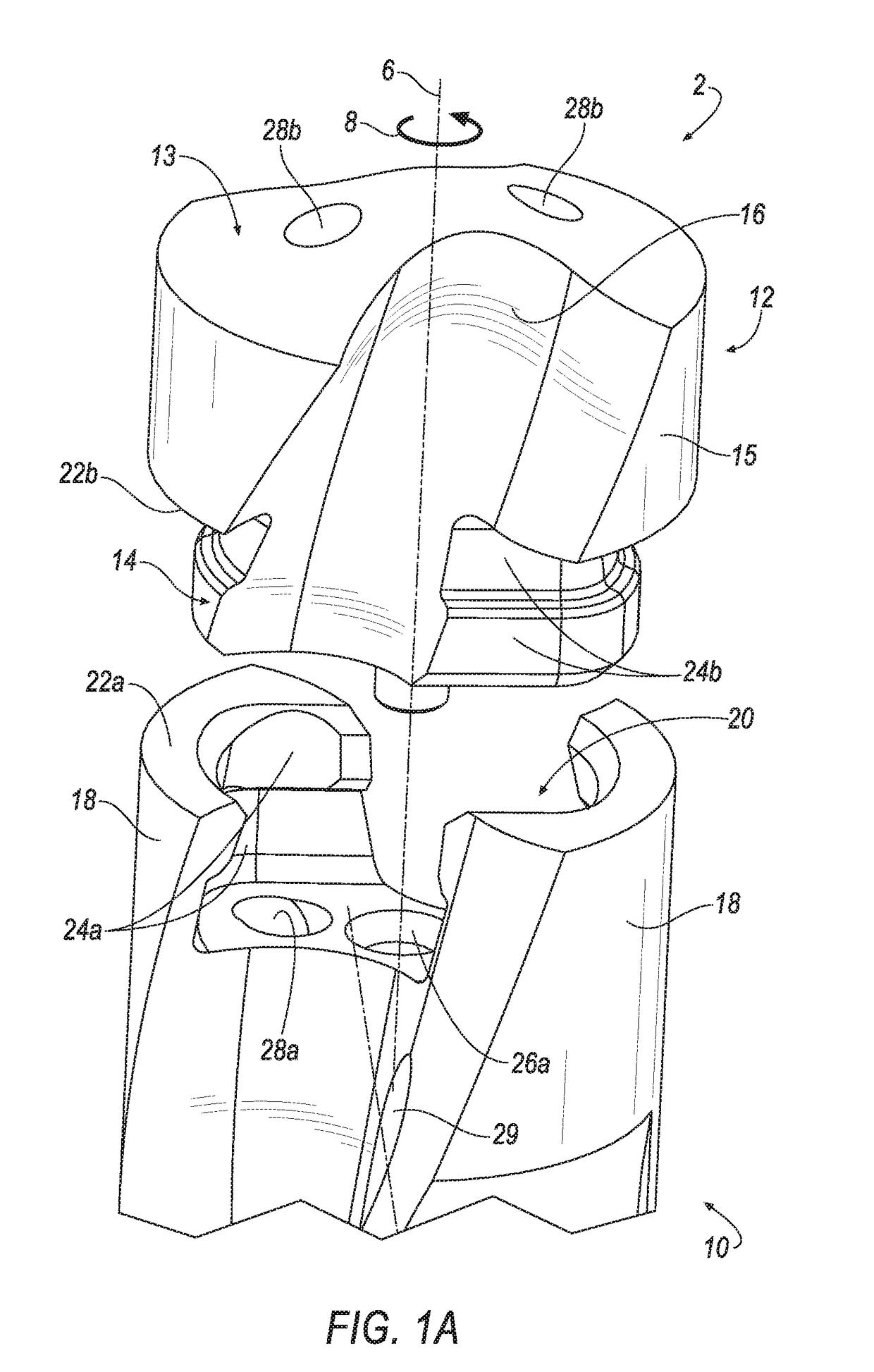
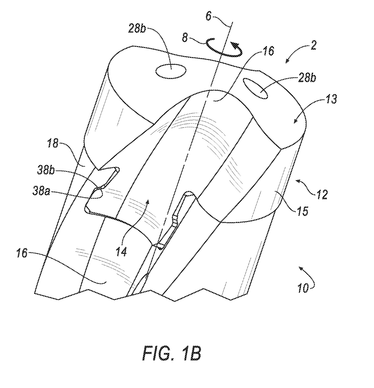
[0023]Referring now to FIGS. 1A and 1B, a rotary tool 2 is shown according to an embodiment of the invention. The rotary tool 2 extends in an axial direction along an axis of rotation 6. The rotary tool 2 rotates around the axis of rotation 6 during normal operation in the direction of rotation, and peripheral direction 8.

[0024]In the illustrated embodiment, the rotary tool 2 comprises a modular rotary drill cutting tool including a support 10 and a cutting head 12 that can be interchangeably mounted to the support 10. However, the invention is not limited to use with a modular rotary drill cutting tool. The rotary tool can also be, for example, a milling tool or another type of rotating tool, for example a reamer, a tap, or the like.

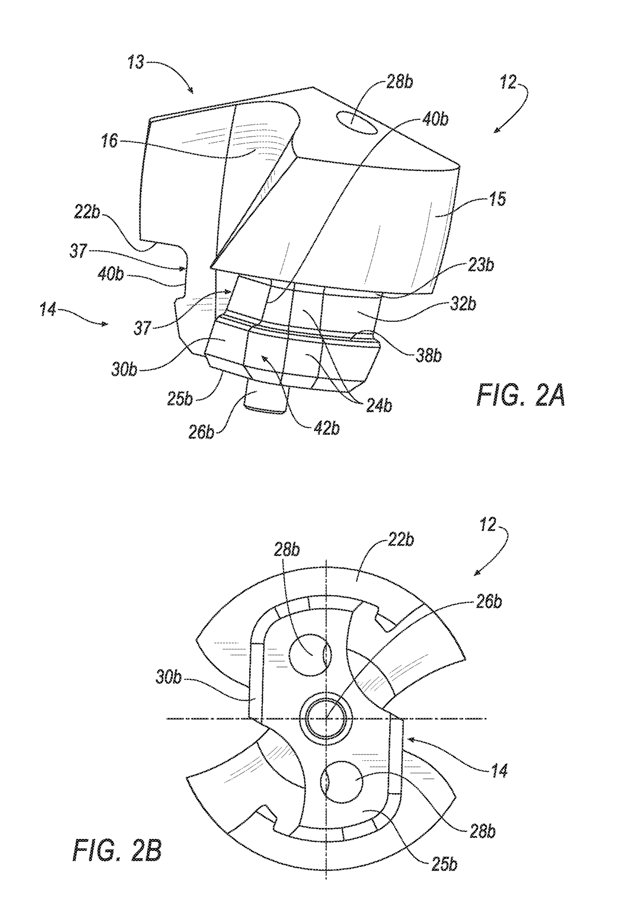
[0025]Referring to FIGS. 1A-2D, the cutting head 12 has a front cutting part 13 and a coupling pin 14 extending axially away from the front cutting part 13 (thus, in an axially rearward direction). The front cutting part 13 of the cutting head 12 define...


PUM


Abstract

A modular rotary cutting tool includes a cutting head for insertion into a support. The cutting head has a coupling pin having torque surfaces and clamping surfaces formed on its outer peripheral surface. The coupling pin is divided into a front pin part and a rear pin part. The front pin part is defined by a circumferential groove. Stop surfaces for an axial pullout prevention are formed between the front pin part and the rear pin part. The torque surfaces and the clamping surfaces are arranged in different pin parts. For example, the clamping surfaces are preferably formed on the front pin part and the torque surfaces are preferably formed on the rear pin part. The clamping surfaces taper radially inward in a direction of the front cutting part at an angle of inclination, α2, with respect to the axis of rotation. Other variants and embodiments are broadly contemplated herein.

Description

FIELD OF THE INVENTION[0001]The invention relates in general to a rotary cutting tool, and in particular to a modular rotary cutting tool, such as a drill, and the like, with a cutting head and a support for accommodating the cutting head.BACKGROUND OF THE INVENTION[0002]One type of rotary tool is a modular rotary tool with two coupling parts; namely, a support and a cutting head. The cutting head is interchangeably mounted in the pocket structure of the support. Unfortunately, in these designs, the radial and axial forces that occur during a drilling operation, especially on uneven or inclined surfaces, may lead to excessive elastic or ultimately plastic deformation of the pocket structure, which can result in peak loads and breakages.SUMMARY OF THE INVENTION[0003]Embodiments of the invention are directed to addressing problems associated with excessive stresses and deformation of the pocket structure by providing clamping surfaces that are inclined with respect to the central, lon...

Claims


Application Information

Patent Timeline
IPC IPC(8): B23B51/02B23C5/28B23C5/02B23Q11/10
CPCB23B51/02B23C5/28B23B2251/02B23Q11/10B23B2251/50B23C5/02
Inventor WACINSKI, MANUELJAEGER, HORSTSCHWAEGERL, JUERGENFILHO, RUY FROTA DE SOUZA
Owner KENNAMETAL INC
Why Eureka
Try Eureka