Supercharge Your Innovation With Domain-Expert AI Agents!

Bearing block assembly

a bearing block and assembly technology, applied in the direction of buffers, railway components, draw-gear, etc., can solve the problems of coupling assembly damage, coupling rod end twisting or canting with the connected bearing components in the bearing block, and the carriage damage, etc., to simplify the design of the bearing shell unit

Active Publication Date: 2019-02-28
VOITH PATENT GMBH
View PDF2 Cites 1 Cited by
  • Summary
  • Abstract
  • Description
  • Claims
  • Application Information

AI Technical Summary

Benefits of technology

This patent describes a bearing arrangement that allows for easy disengagement of the coupling rod in the bearing shell unit when the forces are introduced. This prevents canting in the bearing block and simplifies the design of the bearing arrangement. The guidance region on the bearing shell unit is formed by a solid profile element that is integrated with the bearing shell and has guide surfaces for guiding on the guideway of the bearing block. The tear-off elements extend from the connecting region and are aligned with the guidance direction of the bearing shell, providing reliable avoidance of canting in the bearing shell and the bearing block upon actuation.

Problems solved by technology

It is moreover known that a coupling rod supported rigidly by a bearing block can lead to damage of the carriage or respectively to damage of the coupling assembly itself by the shocks and vibrations that occur, for example, during a coupling procedure or during braking.
However, after actuation of the shear-off or tear-off elements, twisting or canting of the coupling rod end with the connected bearing components in the bearing block cannot be ruled out.

Method used


Image

  • Bearing block assembly
  • Bearing block assembly
  • Bearing block assembly

Examples


Embodiment Construction

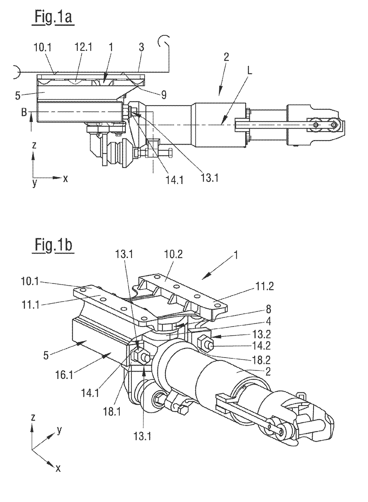
[0049]Referring now to the drawings, and more particularly to FIGS. 1a and 1b there are shown illustrations of the basic construction and basic configuration of a bearing block assembly 1 according to the invention for hinging of a coupling rod 2 of a coupling to a carriage body 3 (that is merely indicated here) of a track guided vehicle, in particular a rail vehicle, showing various views in neutral positions of coupling rod 2, in other words in the non-deflected position. FIG. 1a clarifies the installation position in a longitudinal direction, in which the neutral position of the coupling coincides with a longitudinal axis L of coupling rod 2. For clarification of the individual directions an exemplary coordinate is provided. The X-axis coincides with the longitudinal direction of the coupling, the Y-axis coincides with the lateral direction and thereby with the extension of bearing block assembly 1 transversely to longitudinal axis L; and the Z-direction describes the extension i...


PUM


Abstract

The invention relates to a bearing block assembly for hinging of a coupling rod to a carriage body. The bearing block assembly includes a bearing shell unit and a bearing block with a flange for connecting the bearing block assembly to the carriage body and has an open bearing shell receiving region for at least partial reception of the bearing shell unit. The bearing block assembly has at least one guide extending in a longitudinal direction over at least a section of the extension of the bearing block. The bearing shell unit connects to the bearing block via at least one tear-off element and / or at least one shear-off element and is movably guided on the at least one guide in a longitudinal direction relative to same when the connecting element is actuated, thereby releasing the connection between the bearing shell unit and the bearing block.

Description

CROSS REFERENCE TO RELATED APPLICATIONS[0001]This is a continuation of PCT application No. PCT / EP2017 / 058051, entitled “BEARING BLOCK ASSEMBLY”, filed Apr. 5, 2017, which is incorporated herein by reference.BACKGROUND OF THE INVENTION1. Field of the Invention[0002]The invention relates to a bearing block assembly for hinging of a coupling rod to a carriage body of a track guided vehicle, in particular a rail vehicle.2. Description of the Related Art[0003]Bearing block assemblies in the rail vehicle technology generally serve to connect a coupling rod pivotably in a horizontal plane with the carriage body of a rail guided vehicle. In order for the coupling rod to swivel relative to the carriage body, necessary for example in a multiple-unit train when traveling along curves, the hinging that is provided via the bearing block is generally designed in such a way that at least horizontal and vertical movements as well as axial rotation of the coupling rod relative to the carriage body i...

Claims


Application Information

Patent Timeline
Patent Type & Authority Applications(United States)
IPC IPC(8): B61G9/24
CPCB61G9/24B61G9/10B61G11/16
Inventor WIPFLER, MATHIASAQUINO OLIVEIRA, RENATO
Owner VOITH PATENT GMBH
Features
  • R&D
  • Intellectual Property
  • Life Sciences
  • Materials
  • Tech Scout
  • Unparalleled Data Quality
  • Higher Quality Content
  • 60% Fewer Hallucinations
Learn More