Mobile power generation system including closed cell base structure

a power generation system and closed cell technology, applied in the direction of machine/engine, vehicle maintenance, machine support, etc., can solve the problem of fracturing operation site often occupying a large footprin

Active Publication Date: 2019-02-28
ON POWER INC
View PDF0 Cites 7 Cited by
  • Summary
  • Abstract
  • Description
  • Claims
  • Application Information

AI Technical Summary

Benefits of technology

[0006]In one embodiment, a mobile power generation system may include a trailer including a rear end, a front end, a bottom end, and a top end defining therebetween an interior space, a gas turbine housed inside the trailer in the interior space, an electrical generator coupled to the gas turbine to generate electricity and housed inside the trailer in the interior space, and one or more support jacks configured to support a base at the bottom end of the trailer with respect to a ground. The base may include a closed cell base structure, the closed cell base structure including a rigid surface to be mounted on top of the one or more support jacks, the closed cell base structure configured to include a sufficient amount of torsional stiffness to provide torsional stability and assist with distribution of uneven loads due to variance of forces from the one or more support jacks against the rigid surface.
[0008]In another embodiment, a method for minimizing bending forces associated with support in a mobile power generation system may include providing the mobile power generation system including a trailer including a rear end, a front end, a bottom end, and a top end defining therebetween an interior space, a gas turbine housed inside the trailer in the interior space, an electrical generator coupled to the gas turbine to generate electricity and housed inside the trailer in the interior space, and one or more support jacks configured to support a base at the bottom end of the trailer with respect to a ground, the base including a closed cell base structure, the closed cell base structure including a rigid surface to be mounted on top of the one or more support jacks. The method may further include supporting the base with respect to the ground by placing the one or more support jacks between the ground and the rigid surface of the base at respective one or more trailer support points of the rigid surface, receiving an eccentric load from the one or more trailer support points, and distributing the eccentric load as shear forces as a shear flow across the closed cell base structure that provides a sufficient amount of torsional stiffness to minimize bending associated with variance of forces at each trailer support point.
[0009]In embodiments, the sufficient amount of torsional stiffness may be sufficient to provide torsional stability and assist with distribution of uneven loads due to variance of forces from the one or more support jacks against the rigid surface. The closed cell base structure may include an exterior base include the rigid surface, intermediate side walls extending upwardly from side ends of the exterior base, and end exterior side walls extending upwardly from outer ends of the exterior base, and the shear flow may follow a circulatory path. The circulatory path may be along the exterior base toward one wall of the end exterior side walls, upwardly along the one wall of the end exterior side walls, along top surfaces of the intermediate side walls toward an opposite wall of the end exterior side walls, and downwardly toward the exterior base.

Problems solved by technology

The fracturing operation site often encompasses a large footprint with the number of wellbores and supporting components.

Method used


Image

  • Mobile power generation system including closed cell base structure
  • Mobile power generation system including closed cell base structure
  • Mobile power generation system including closed cell base structure

Examples


Embodiment Construction

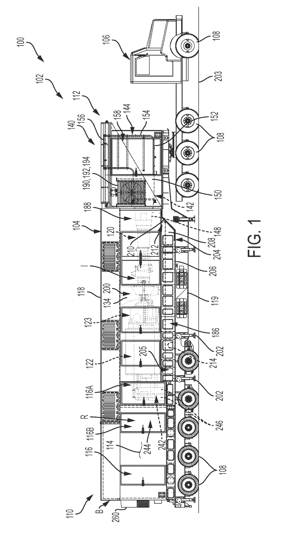
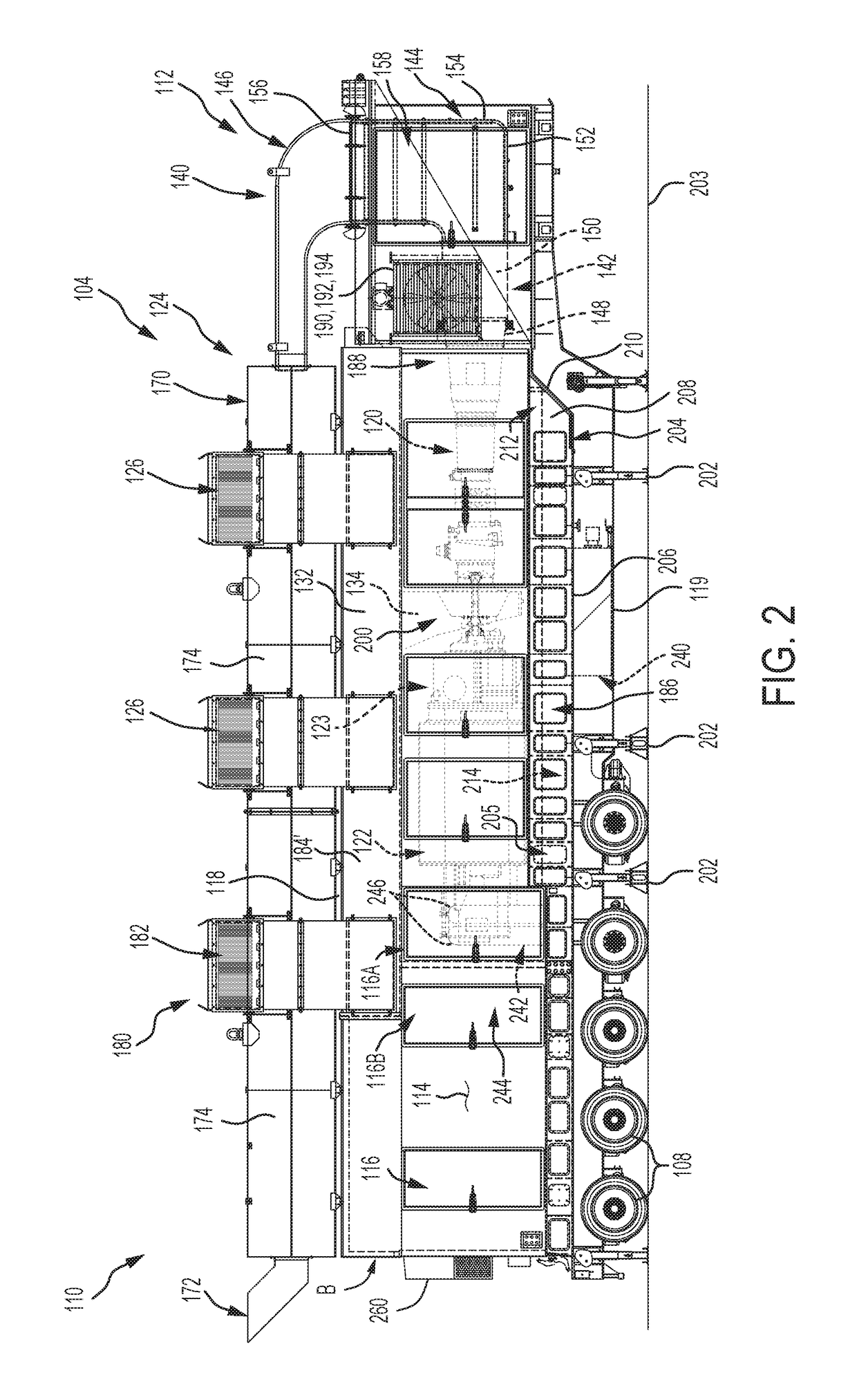
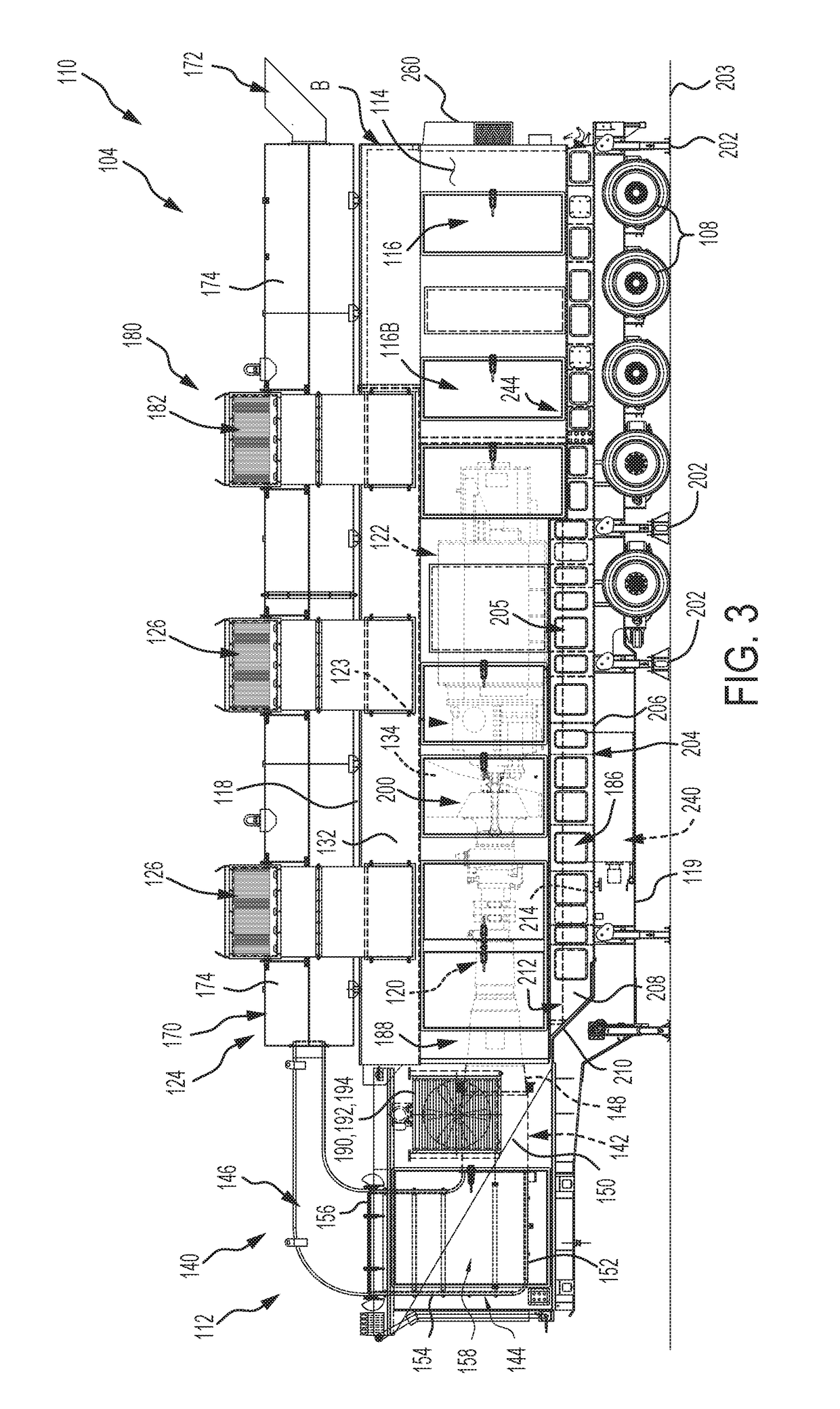
[0029]Referring initially to FIG. 1, a mobile power generation system 100 described herein includes a mobile unit 102 that may include a trailer 104 coupled to a tractor 106, each of the trailer 104 and tractor 106 including a plurality of wheels 108. The trailer 104 includes a rear end 110, a front end 112 to which the tractor 106 is configured to be attached, and side panels 114 disposed between the rear end 110 and front end 112. The side panels 114 each comprises one or more access doors 116 configured to access areas of the mobile power generation system 100 housed inside the trailer 104. The trailer 104 further includes a top end 118 and a bottom end 119 respective disposed along top and bottom portions of the side panels 114 and connecting the front end 112 to the rear end 110.

[0030]A power control room 244 including, among other components, switchgear, may be positioned at the rear end 110 of the trailer 104 and may be maintained as a regulated portion R at a desired room te...


PUM


Abstract

Mobile power generation systems and methods for minimizing bending forces associated with support include providing a trailer including a rear end, a front end, a bottom end, and a top end, a gas turbine housed inside the trailer, an electrical generator coupled to the gas turbine to generate electricity and housed inside the trailer, and one or more support jacks configured to support a base at the bottom end of the trailer with respect to a ground. The base includes a closed cell base structure, the closed cell base structure including a rigid surface to be mounted on top of the one or more support jacks, the closed cell base structure configured to include a sufficient amount of torsional stiffness to provide torsional stability and assist with distribution of uneven loads due to variance of forces from the one or more support jacks against the rigid surface.

Description

TECHNICAL FIELD[0001]The present specification generally relates to power generation systems, and more specifically to mobile power generation systems for operations that may use remotely generated power, such as fracking.BACKGROUND[0002]The present disclosure relates generally to a mobile power generation system, and more particularly to a gas turbine-based mobile power generation system that can provide electrical power through a generator to a plurality of electrically driven motors operating as, for example, fluid pumps in a fracturing operation (also referable to as fracking). Such remotely generated power may be in addition to or an alternative of power from the grid.[0003]In a fracturing operation, a fluid and additive slurry including sand is injected at a wellbore into a rock formation that bears hydrocarbon to allow for fracturing as the sand remains in a created fracture in a flow path in the wellbore while most of the other injected fluids flow back and are recovered fro...

Claims


Application Information

Patent Timeline
Patent Type & Authority Applications(United States)
IPC IPC(8): F02C7/20F02C7/12F02C7/32F02C6/20F02C6/14B60S9/04
CPCF02C7/20F02C7/12F02C7/32F02C6/20F02C6/14B60S9/04F05B2240/941F05D2220/76F16M3/00F16M5/00F16M9/00F01D15/10F01D25/28F02C6/00F05D2250/75
Inventor DAVIS, LARRY D.
Owner ON POWER INC
Why Eureka
Try Eureka