Inflation valve seat with adjustable flow

Active Publication Date: 2019-02-28
SHENZHEN QREM TECH CO LTD
View PDF0 Cites 2 Cited by
  • Summary
  • Abstract
  • Description
  • Claims
  • Application Information

AI Technical Summary

Benefits of technology

[0013]By opening and closing the intercommunicating valve of the present invention, the disconnected state and the communicated state between the first air channel and the second air channel are controlled to further selectively

Problems solved by technology

However, in the above air valves, an air pump is primarily used to coordinate with at least one air valve to inflate and deflate at least one air bag, and

Method used


Image

  • Inflation valve seat with adjustable flow
  • Inflation valve seat with adjustable flow
  • Inflation valve seat with adjustable flow

Examples


Example

[0021]Details and technical contents of the present invention are given with the accompanying drawings below.

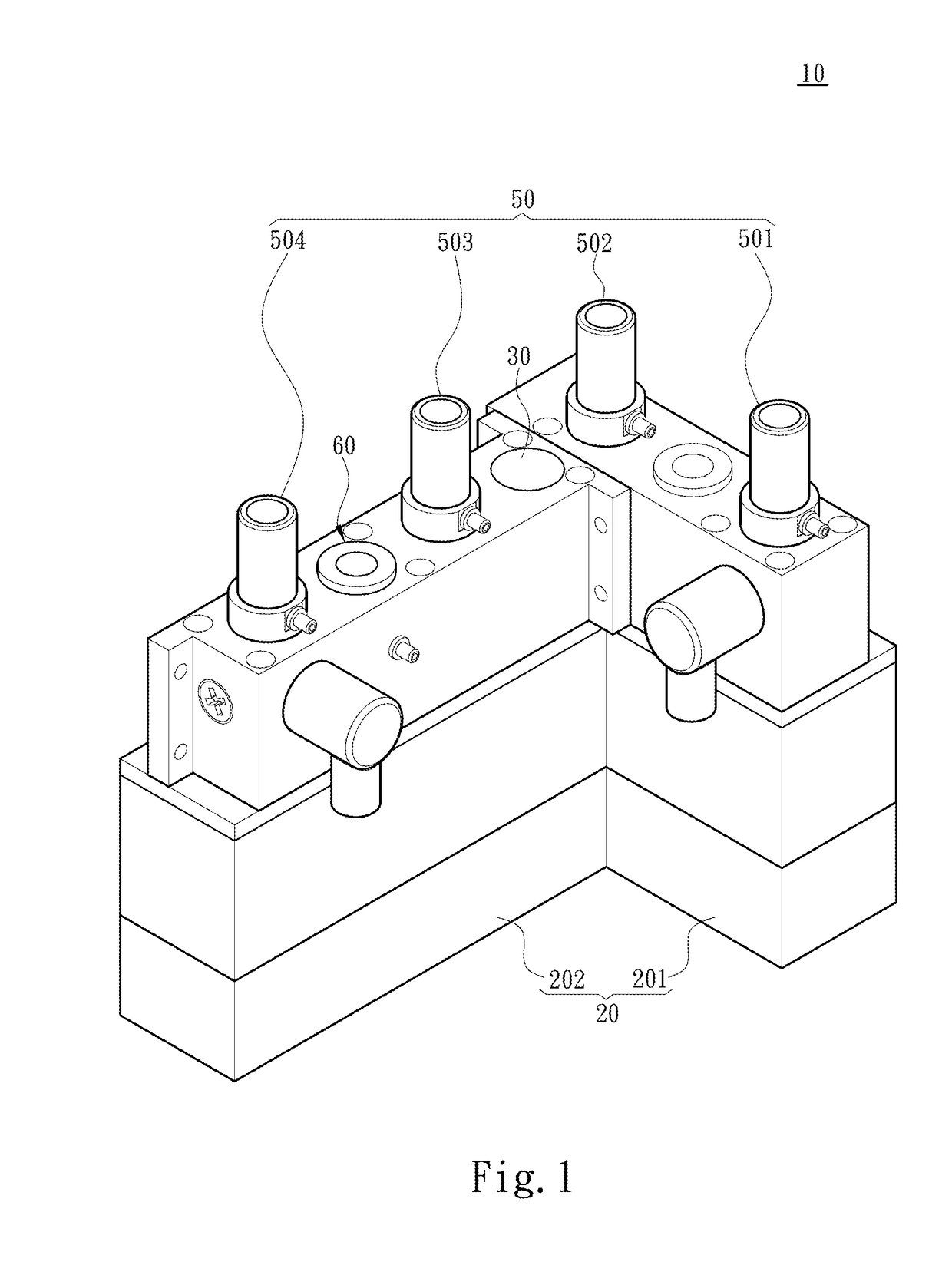
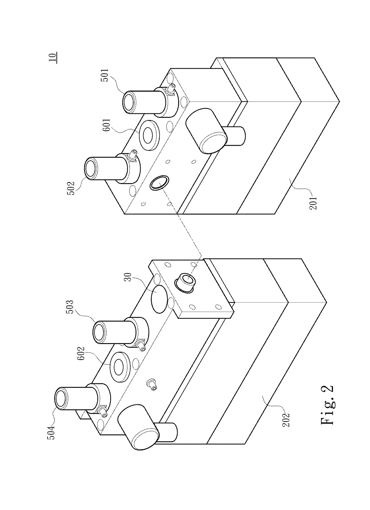
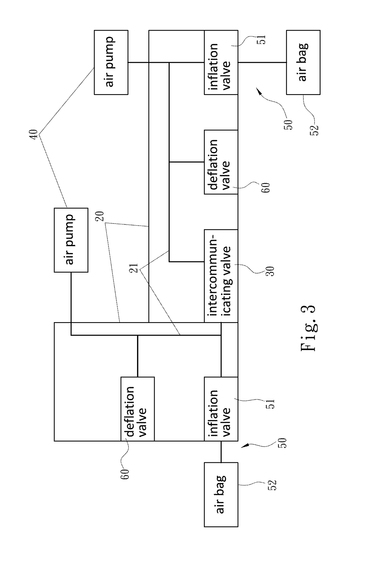
[0022]Referring to FIG. 1 to FIG. 3, the present invention provides an inflation valve seat 10 with adjustable flow. The inflation valve seat 10 includes two valve seats 20 and an intercommunicating valve 30. Each of the valve seats 20 is connected to an air pump 40, and includes at least one inflation valve assembly 50, a deflation valve 60, and an air channel 21 in communication with the air pump 40, the inflation valve assembly 50 and the deflation valve 60. Each of the inflation valve assemblies 50 further includes at least one inflation valve 51 and at least one air bag 52. The inflation valve 51 is in communication with the air channel 21, and the air bag 52 is in connected to the inflation valve 51, such that each valve seat 20 has an inflating state and a deflating state. In the inflating state, a gas is introduced by the air pump 40, and passes through the air channe...


PUM


Abstract

An inflation valve seat with adjustable flow includes two valve seats and an intercommunicating valve. Each valve seat is connected to an air pump, and includes an inflation valve assembly, a deflation valve, and an air channel in communication with the air pump, the inflation valve assembly and the deflation valve. The intercommunicating valve is connected between the two valve seats to provide a disconnected state and a communicated state between the two valve seats. When the two air channels form the disconnected state, the two valve seats have a low-flow inflating state and a low-flow deflating state. When the two air channels form the communicated state, the two valve seats have a high-flow inflating state and a high-flow deflating state.

Description

FIELD OF THE INVENTION[0001]The present invention relates to an inflation valve seat, and particularly to an inflation valve seat capable of adjusting inflation and deflation air flow.BACKGROUND OF THE INVENTION[0002]An air valve is primarily used for inflating and deflating at least one air bag to provide an air cushion with appropriate softness, e.g., an inflatable mattress, an inflatable sofa and an inflatable cushion.[0003]With respect to a common air valve, an inflation valve is generally connected to an air pump and an air bag, so as to achieve inflation of the air bag through introducing a gas by the air pump and via the inflation valve, and to prevent the gas having entered the air bag from leaking by the inflation valve. To deflate the air bag, a deflation valve is additionally connected on the air bag or on the inflation valve, so as to allow the gas in the air bag to pass through the deflation valve to achieve deflation.[0004]For example, the China Patent No. CN105443807,...

Claims


Application Information

Patent Timeline
IPC IPC(8): F16K11/22F16K27/00F16K15/20
CPCF16K11/22F16K27/003Y10T137/86139Y10T137/87169Y10T137/86131F16K15/207B60N2/914
Inventor YIN, ZU-JUN
Owner SHENZHEN QREM TECH CO LTD
Why Eureka
Try Eureka