Time-based access of a memory cell

Active Publication Date: 2019-02-28
MICRON TECH INC
View PDF2 Cites 7 Cited by
  • Summary
  • Abstract
  • Description
  • Claims
  • Application Information

AI Technical Summary

Problems solved by technology

Memory devices may be volatile or non-volatile.
Volatile memory devices, e.g., DRAM, may lose t

Method used


Image

  • Time-based access of a memory cell
  • Time-based access of a memory cell
  • Time-based access of a memory cell

Examples


Embodiment Construction

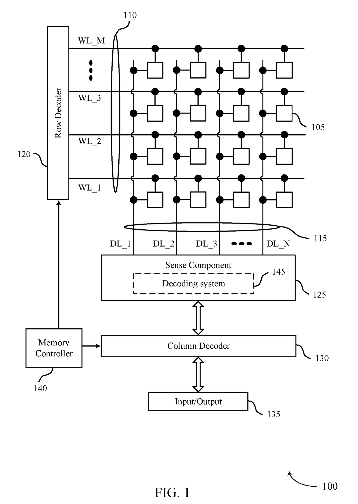
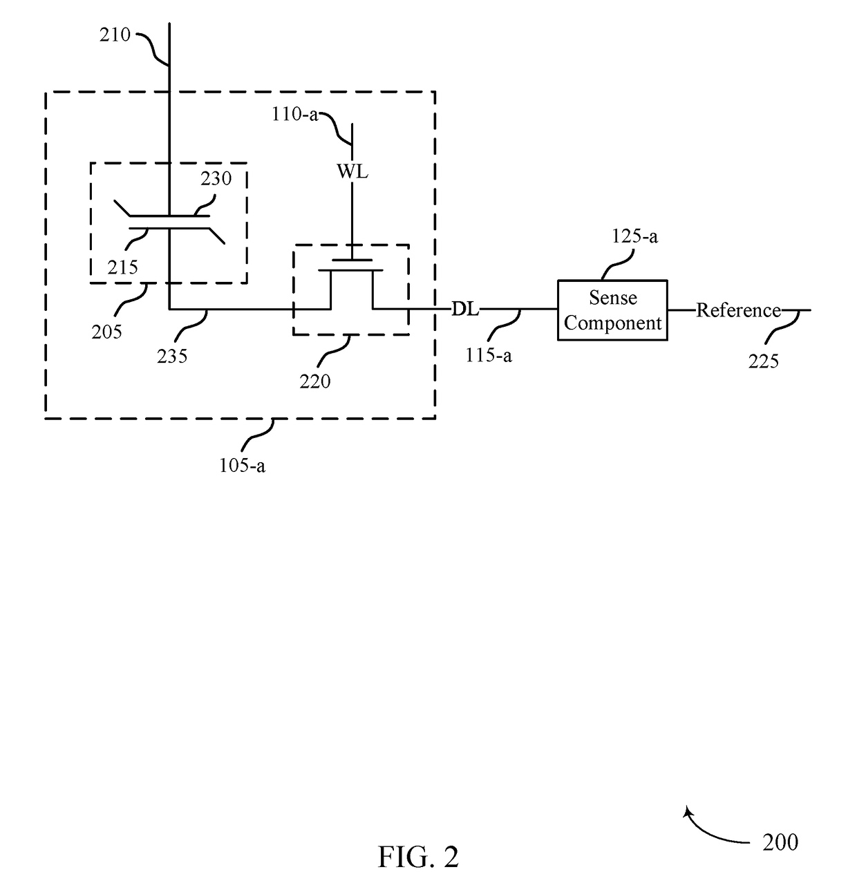
[0018]Memory devices generally use voltages to distinguish between logic states stored on memory cells. For example, during a read operation of a memory cell, a memory controller may cause the memory cell to discharge a charge or a voltage onto an access line. The memory controller may identify the logic state stored on the memory cell based on a comparison between the voltage of the access line and a reference voltage. In some examples, using voltage levels to distinguish between logic states of memory cells may limit how many unique logic states may be stored on a memory cell.

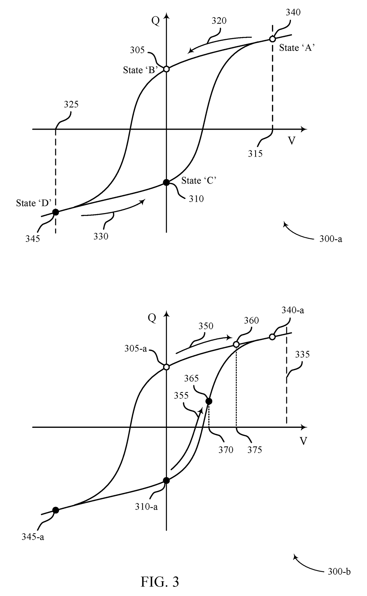
[0019]Techniques, systems, and devices for time-resolved access of memory cells in a memory array are described herein. During a sense portion of a read operation, a selected memory cell may be charged to a predetermined voltage level. A logic state stored on the selected memory cell may be identified based on a duration between the beginning of the charging and when selected memory cell reaches the predeterm...


PUM


Abstract

Techniques, systems, and devices for time-resolved access of memory cells in a memory array are described herein. During a sense portion of a read operation, a selected memory cell may be charged to a predetermined voltage level. A logic state stored on the selected memory cell may be identified based on a duration between the beginning of the charging and when selected memory cell reaches the predetermined voltage level. In some examples, time-varying signals may be used to indicate the logic state based on the duration of the charging. In some examples, the duration of the charging may be based on a polarization state of the selected memory cell, a dielectric charge state of the selected state, or both a polarization state and a dielectric charge state of the selected memory cell.

Description

CROSS REFERENCE[0001]The present Application for patent is a divisional of and claims priority to and the benefit of U.S. patent application Ser. No. 15 / 619,163 by Di Vincenzo, entitled “Time-Based Access of A Memory Cell,” filed Jun. 9, 2017, which is related to co-pending U.S. patent application Ser. No. 15 / 619,158 by Di Vincenzo, entitled “TIME-BASED ACCESS OF A MEMORY CELL,” assigned to the assignee hereof, each of which is expressly incorporated by reference herein.BACKGROUND[0002]The following relates generally to time-based access of a memory cell and more specifically to time-based sensing of a logic state of the memory cell.[0003]Memory devices are widely used to store information in various electronic devices such as computers, wireless communication devices, cameras, digital displays, and the like. Information is stored by programming different states of a memory device. For example, binary devices have two states, often denoted by a logic “1” or a logic “0.” In other sys...

Claims


Application Information

Patent Timeline
IPC IPC(8): G11C11/22
CPCG11C11/2293G11C11/2273G11C11/221G11C11/2259G11C11/5657G11C11/005
Inventor DI VINCENZO, UMBERTO
Owner MICRON TECH INC
Why Eureka
Try Eureka