Apparatus and method for detecting or recognizing pattern by employing a plurality of feature detecting elements

a technology apparatus, applied in the field of apparatus and method for detecting or recognizing patterns by employing a plurality of feature detecting elements, can solve the problems of limited information processing capability, no methods available, and application limitation to digital representation of information

Inactive Publication Date: 2002-03-28
CANON KK
View PDF23 Cites 282 Cited by
  • Summary
  • Abstract
  • Description
  • Claims
  • Application Information

AI Technical Summary

Problems solved by technology

In implementing the prior arts mentioned above by using circuitry or the like, especially concerning the application to image recognition, there have been no methods available for representing information regarding a two-dimensional pattern by utilizing dynamic characteristic on a time base, and using the represented information for recognition or the like at any level of an a processing device, a module, or a system, which makes up a function of each processing unit (e.g. the extraction of a feature).
In addition, the application has been limited to the processing in a domain of digital representation of information.
For the reason described above, the information processing capability has been limited, and the implementation in the form of circuitry tends to inevitably involve an unduly large scale and high cost.
In particular, the proportion of a large number of wiring for the connection among neurons has been considerably high in the entire area, and this has been posing a problem.
The AER, however, has been presenting a problem in that a device for sequentially coding and decoding the addresses of neurons is required, making a circuit configuration complicated.
However, no literature, including the literature concerning PCNN mentioned above has disclosed any specific configurations based on a neural network in a method for implementing a recognition function by utilizing analog information, such as the interval between spikes, of a train of spikes in a time base domain for the coding or the like of image information in a neural network model for carrying out predetermined processing by inputting, outputting, or transmitting trains of spikes.
Thus, a method in which the conventional predetermined mapping conversion (conformal mapping conversion, etc.) is performed to implement pattern recognition wherein recognition performance is invariant on objects to be recognized that have different scales has been posing a problem in that it is difficult to obtain scale-invariant features unless the central point of conversion is properly set.
The method based on the template matching has been presenting a problem in terms of practicality in that, when performing matching with the template models in different scales that have been represented beforehand, high recognition performance cannot be achieved unless an object in an input image substantially matches with one of the scales, meaning that numerous different template models are required.
This method, however, has been presenting a problem in that the dimension of covariance matrix is large (e.g., 16,384 dimensions in the case presented by Murase and Nayar in 1995), inevitably requiring enormously high cost for calculating eigenvectors.
This has been requiring an extremely large memory space and an enormously long time for computation to complete the processing.
Therefore, to perform scale-invariant recognition, it is necessary to provide a sufficiently high multiplexing level of resolutions to be prepared beforehand, leading to poor processing efficiency.
For this reason, the method may be suited for acquiring rough information by using less memories, but unsuited for recognition or detection requiring high accuracy.
The method based on the dynamic routing network (Anderson et al., 1995; Olshausen et al., 1995) requires a mechanism for dynamically setting the connection between nerve cell elements between predetermined scale levels by a local competing proc

Method used


Image

  • Apparatus and method for detecting or recognizing pattern by employing a plurality of feature detecting elements
  • Apparatus and method for detecting or recognizing pattern by employing a plurality of feature detecting elements
  • Apparatus and method for detecting or recognizing pattern by employing a plurality of feature detecting elements

Examples


first embodiment

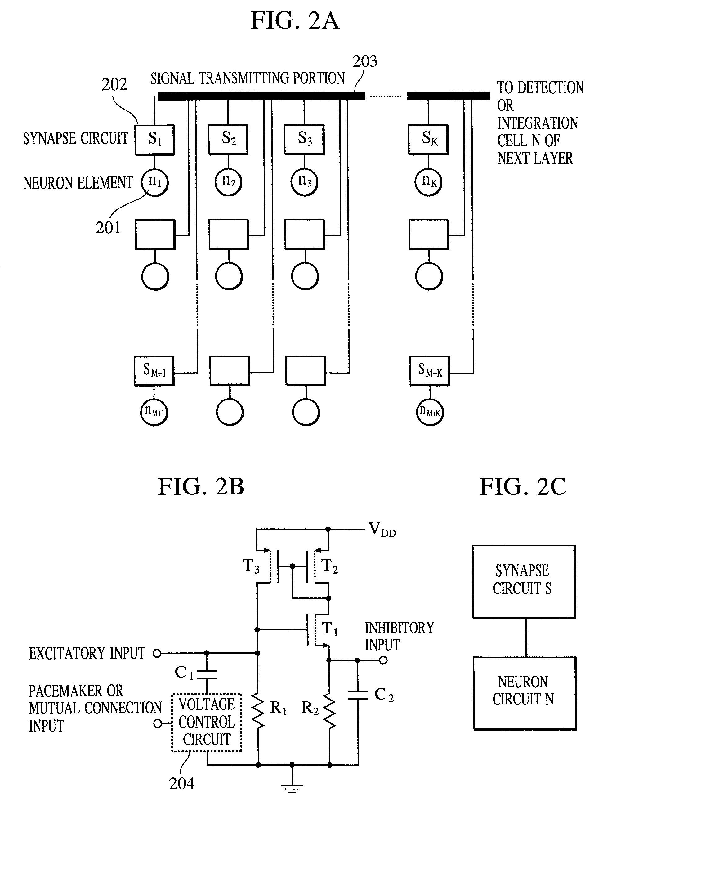
[0225] The modulation by a synapse is expressed by W.sub.a=S.sub.ijW.sub.b when the pulse width of a pre-synaptic signal is denoted as W.sub.b, and the pulse width of a post-synaptic signal is denoted as W.sub.s. In this case, S.sub.ij means the same as the connection strength in expression (5) of the To take a wide dynamic range for the modulation, the basic pulse width of a pulse signal must be set to a value that is sufficiently smaller than the period, i.e., a basic pulse interval.

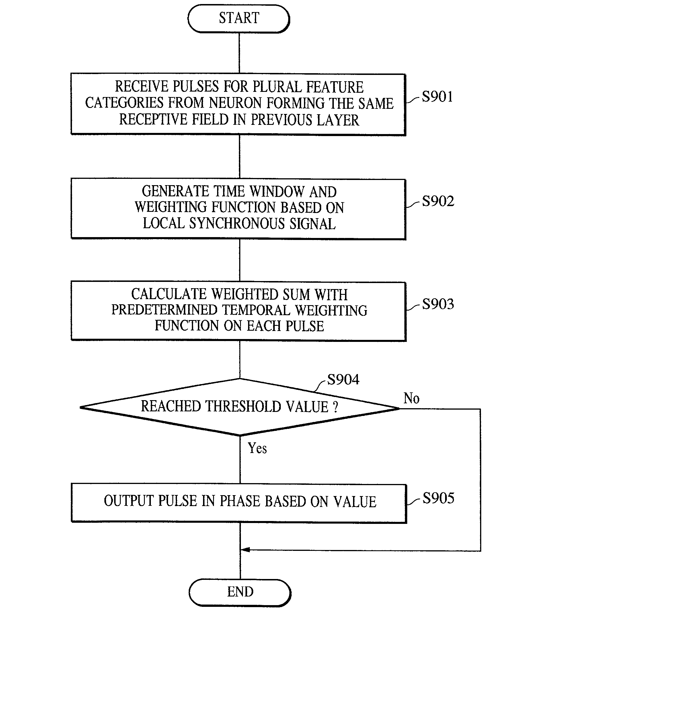
[0226] A neuron fires or outputs a pulse when its potential exceeds a predetermined threshold value because of the charges accumulated due to the inflow of a plurality of pulse currents that represent predetermined feature elements. This embodiment does not particularly need the weighted addition of arrived pulses for each sub time window, which has been described in the first embodiment, but implements integration in a time window having a predetermined width. In this case, a feature element or a gra...

fourth embodiment

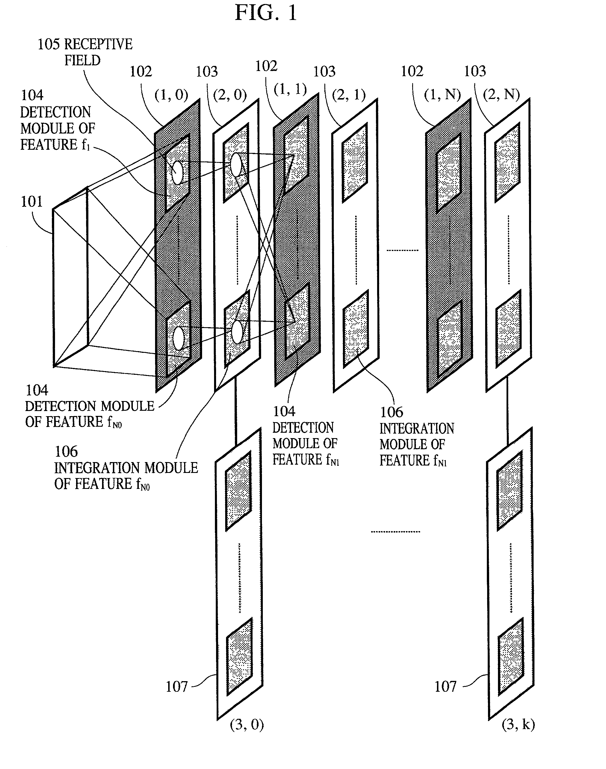
[0245] The general configuration of the pattern detecting or recognizing apparatus is identical to that shown in FIG. 1.

[0246] In this embodiment, the feature detection layers (1,0), (1,1), . . . and feature integration layers (2,0), (2,1), . . . shown in FIG. 1 form a set of processing channels at a plurality of resolutions or scale levels as a whole. Each processing channel implements processing at one scale level or resolution to detect and recognize low- to high-order features by hierarchical parallel processing.

[0247] Each layer has a plurality of circuit elements that belong to different processing channels, the circuit elements being disposed in a predetermined layout. Referring now to the examples shown in FIG. 15 and FIG. 16, the configuration of the processing channels will be described in conjunction with the feature integration layer (2,0).

[0248] Both examples shown in FIG. 15 and FIG. 16 form one processing channel with a subsequent layer if the scale level or the reso...

fifth embodiment

[0315] FIG. 21 shows a network configuration employed in the More specifically, in a feature detection layer (1,k), wherein "k" is a natural number, features are detected that are higher-order than the features obtained by the Gabor wavelet transform or the like and extracted from a layer (1,0). As shown in FIG. 21, however, from a layer (1,1) and after, it is possible to eliminate physical differences among processing channels in circuit configuration.

[0316] Referring to FIG. 21, S.sub.k,m is detected in a layer (1,0), and it indicates a feature category of a scale level m and of a k-th feature category. C.sub.k,m is integrated in a layer (2,0), and it indicates a feature category of a scale level m and of a k-th feature category. From a layer (1,1) and after, the feature categories to be detected and integrated have no scale level indices attached thereto.

[0317] FIG. 23 shows the transition of signal trains. In order to obtain scale-invariant representation of information by puls...


PUM


Abstract

A pattern detecting apparatus has a plurality of hierarchized neuron elements to detect a predetermined pattern included in input patterns. Pulse signals output from the plurality of neuron elements are given specific delays by synapse circuits associated with the individual elements. This makes it possible to transmit the pulse signals to the neuron elements of the succeeding layer through a common bus line so that they can be identified on a time base. The neuron elements of the succeeding layer output the pulse signals at output levels based on a arrival time pattern of the plurality of pulse signals received from the plurality of neuron elements of the preceding layer within a predetermined time window. Thus, the reliability of pattern detection can be improved, and the number of wires interconnecting the elements can be reduced by the use of the common bus line, leading to a small scale of circuit and reduced power consumption.

Description

[0001] 1. Field of the Invention[0002] The present invention relates to an apparatus and a method mainly designed for recognizing a pattern or detecting a particular subject by using a parallel arithmetic device, such as a neural network.[0003] 2. Description of the Related Art[0004] Hitherto, in the field of image recognition or speech recognition, the methods available for implementing such recognition have been roughly classified into two types. In one type, such recognition is implemented by performing serial arithmetic operation by employing, as a computer software program, a recognition processing algorithm tailored to a specific object to be recognized. In the other type, such recognition is implemented using a dedicated parallel image processor, such as a single instruction multiple data stream (SIMD) machine or a multiple instruction multiple data stream (MIMD) machine.[0005] The following will describe typical examples of image recognition algorithms. First, examples where...

Claims


Application Information

Patent Timeline
IPC IPC(8): G06K9/00G06K9/46G06K9/66
CPCG06K9/00973G06K9/4628G06N3/049G06N3/063G06V10/94G06V10/454
Inventor MATSUGU, MASAKAZU
Owner CANON KK
Why Eureka
Try Eureka