Attachment system with a connected article

a technology of connecting system and attached article, which is applied in the direction of buckles, snap fasteners, instruments, etc., can solve the problems of unavoidable damage to the strength of connection and buckle stability, and the need to replace the whole buckle, so as to facilitate the detection of the location of the device and the effect of opening

Active Publication Date: 2019-03-07
DURAFLEX HONG KONG
View PDF2 Cites 2 Cited by
  • Summary
  • Abstract
  • Description
  • Claims
  • Application Information

AI Technical Summary

Benefits of technology

[0005]This object is accomplished by an attachment system comprising a primary device and a secondary device connected to the primary device in a pivoting manner. The primary device has a main body, a front, a rear, two lateral sides and a bar for attaching the primary device to another object. Each of the lateral sides has a protrusion extending laterally outward from the lateral sides. The secondary device has two lateral sides and a top bar connecting the two lateral sides. Each of the lateral sides is equipped with an aperture that corresponds to one of the protrusions on the primary device, so that fitting the protrusions into the apertures pivotally connects the primary device to the secondary device, with the lateral sides of the secondary device being disposed outside of the lateral sides of the primary device. The secondary device can be pivoted between a folded position where the secondary device lies against the primary device, and an open position where the secondary device is raised up from the primary device. The secondary device can be rotation about a wide angle, without affecting the position of the buckle.
[0007]In a preferred embodiment, the primary device is a two-piece buckle, with a male portion and a female portion, and in particular, a side-release buckle in which locking legs of the male portion protrude through side slots in the female portion. The secondary device is connected to the exterior of the lateral sides of the male portion. The female portion has a front side and a rear side, and the front side has an indentation corresponding to a shape of the secondary device, so that in a folded position, the secondary device rests in the indentation of the female portion. When the secondary device is closed, it lays on the top surface of the buckle in the indentation. Part of the secondary device is hidden and is surrounded by the buckle, and as a result protection to the critical part of the secondary device is formed. In addition, in this design, the male buckle portion has both legs and a center guidance piece, so that the strength and stability is maintained, even with the addition of the secondary device.
[0008]Preferably, the top bar of the secondary device extends beyond a top edge of the male portion, so that pressing down on the bar causes the secondary device to pivot from a folded position to an open position. This eliminates the need for the user to pry up the free end of the secondary device in order to use it.
[0010]The present invention has many benefits over prior devices. For example, since the secondary device is a separate part and can be replaceable, the user can have an option to change the device with another secondary device based on the user's need. The secondary device is placed on top of the primary device, so the user can easily detect the location of the device and open it. In addition, the location of the secondary device does not affect the structure or operation of the primary device. The user can raise the secondary device to the raised position and have full access to all sides of the primary device for attachment to a strap or other item.

Problems solved by technology

The problem with this single piece arrangement is that if the additional device is damaged, the whole buckle has to be replaced.
The problem with these devices having the embedded accessories is that it is very difficult for the user to find and also open the device, especially in the circumstances when the user can only use their hand to find the buckle without seeing it, such as when the buckle is used on the sternum strap of a backpack.
In this case, the strength of the connection and the stability of the buckle is unavoidably affected.

Method used


Image

  • Attachment system with a connected article
  • Attachment system with a connected article
  • Attachment system with a connected article

Examples


Embodiment Construction

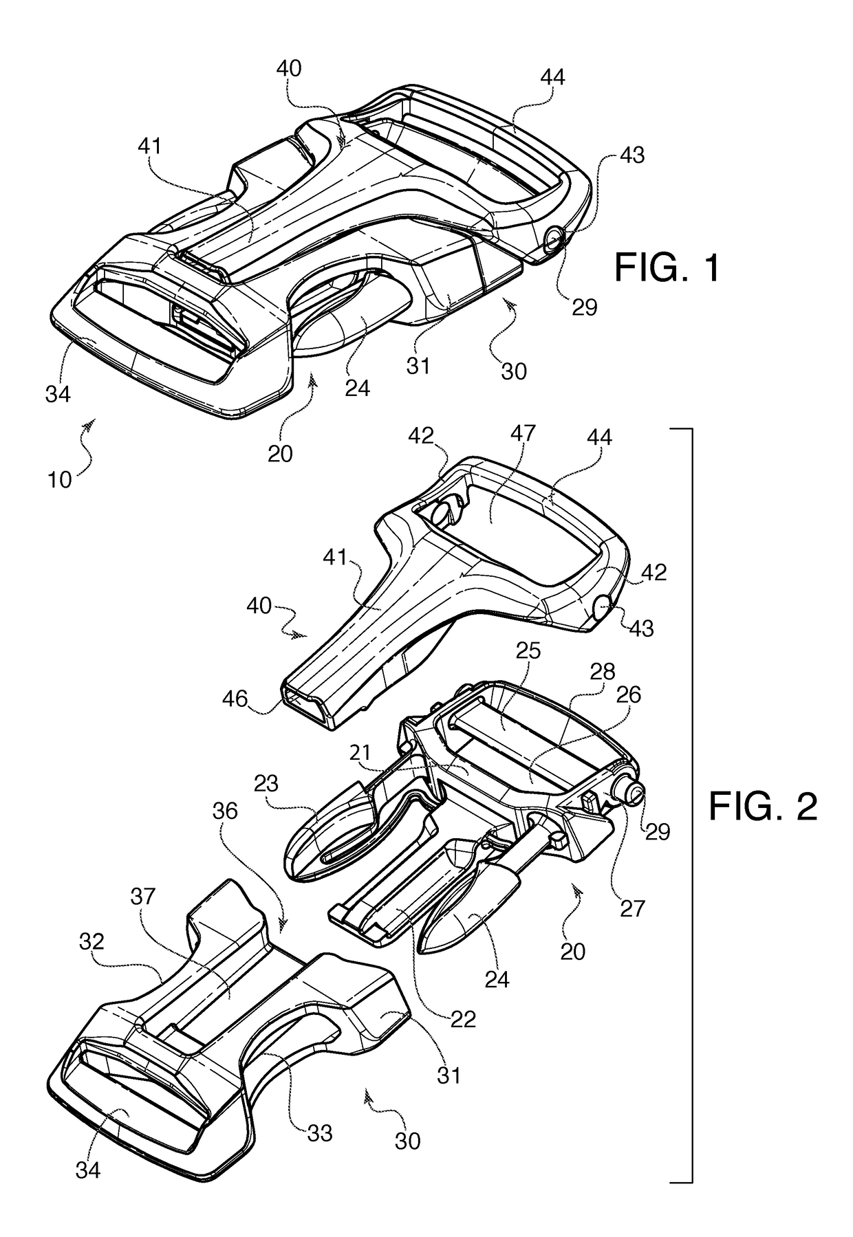
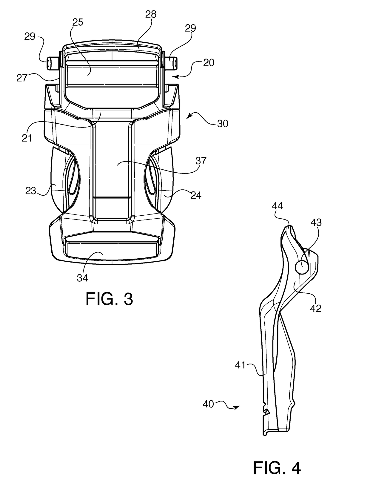
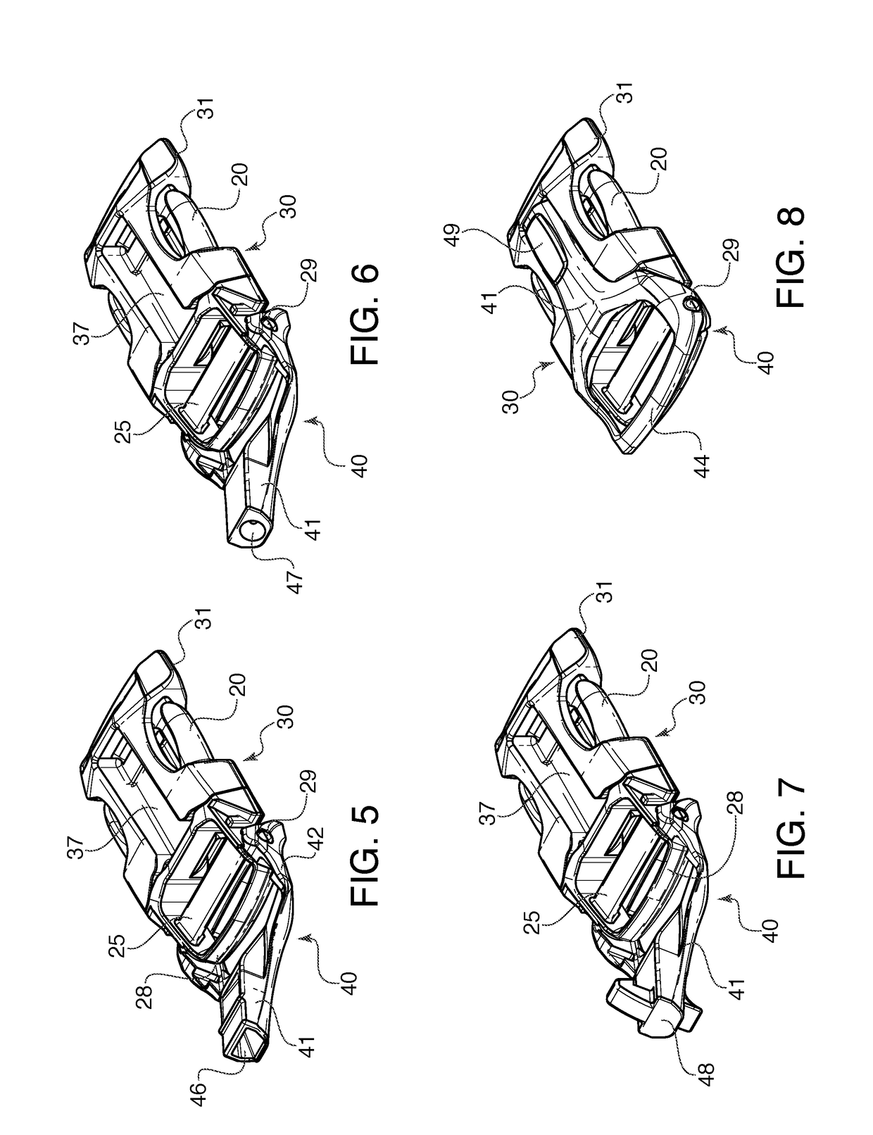
[0026]Referring now in detail to the drawings, FIGS. 1-5 show a first embodiment of the system 10 according to the invention. System 10 comprises a buckle having a male portion 20, a female portion 30, and a secondary device 40 in the form of a whistle. Male portion 20 is formed of a main body 21 with a central guide 22, two locking legs 23, 24, an attachment bar 25 spanning an opening 26 bounded by side walls 27, and a top edge 28. On each side wall 27 is a protrusion 29 extending outwardly.

[0027]Female portion 30 is formed of a hollow main body 31 having openings 32, 33 for receiving locking legs 23, 24 and an attachment bar 34 at its end. An opening 36 receives male portion 20 to lock male portion 20 to female portion 30 when locking legs 23, 24, snap into openings 32, 33. Guide flanges (not shown) are disposed inside female portion 30 to guide central guide 22 of male portion 20 as it is inserted into female portion 30. A longitudinal indentation 37 runs down the length of femal...


PUM


Abstract

An attachment system is formed by a primary device and a secondary device connected to the primary device in a pivoting manner. The primary device has a main body, two lateral sides and a bar for attaching the primary device to another object. Each of the lateral sides has a protrusion extending laterally outward from the lateral sides. The secondary device has two lateral sides, each equipped with an aperture that corresponds to one of the protrusions on the primary device, so that fitting the protrusions into the apertures pivotally connects the primary device to the secondary device, with the lateral sides of the secondary device being disposed outside of the lateral sides of the primary device. The secondary device can be pivoted between a folded position where the secondary device lies against the primary device, and an open position where the secondary device is raised up.

Description

BACKGROUND OF THE INVENTION1. Field of the Invention[0001]The present invention relates to a buckle or other attachment system having an article attached to the buckle. In particular, the invention relates to a buckle in which an article is pivotally connected to the buckle, so that the article can be pivoted into a useful position and then pivoted back against the buckle when not in use.2. The Prior Art[0002]It is often desirable to attach articles such as clips lights and whistles to buckles or other attachment devices, to improve their utility. U.S. Pat. No. 6,668,428 to Moeller shows a buckle having a whistle integrally formed therewith. The whistle is formed at an end of the female member and extends crosswise across the buckle. The problem with this single piece arrangement is that if the additional device is damaged, the whole buckle has to be replaced.[0003]JP5852801B2 shows a whistle pivotally connected to a buckle. This whistle is connected to the female portion of the buc...

Claims


Application Information

Patent Timeline
Patent Type & Authority Applications(United States)
IPC IPC(8): A44B11/00F16G11/08F16G11/04A44B11/04A44B11/25
CPCA44B11/005F16G11/08A44D2201/04A44B11/04A44B11/2592F16G11/046A44B11/266F16G11/02F16G11/101G10K5/00
Inventor CHAN, YICK FAIWONG, YING KWAN
Owner DURAFLEX HONG KONG
Why Eureka
Try Eureka