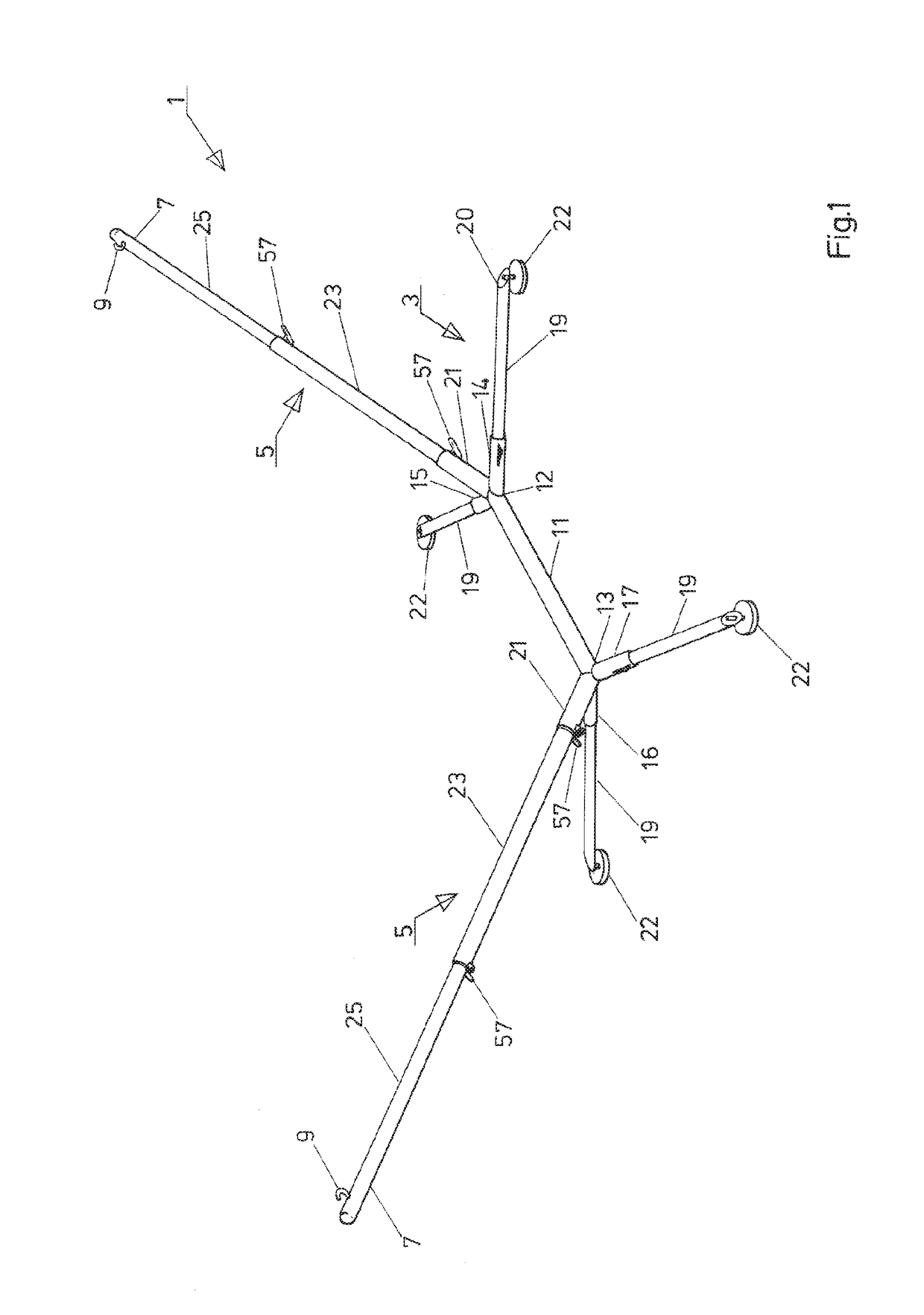
[0025]FIG. 1 shows an embodiment of a dismountable hammock stand. The stand 1 comprises a base to be placed on a floor, and two bars 5 extending from the base 3, wherein a hook 9 is fixed to an end portion 7 of each bar 5. A hammock, not shown in FIG. 1, can be attached to the hooks. The hooks 9 are located at a height of about 1.5 meters above the floor and at a distance of about 4 meters from each other.
[0026]The base 3 comprises a main tube 11 having a first end 12 and a second end 13, wherein a first tube socket 14 and a second tube socket 15 are mounted on the first end 12 of the main tube 11, and wherein a third tube socket 16 and a fourth tube socket 17 are mounted on the second end 13 of the main tube 11. Four leg tubes 19 are provided, wherein each leg tube 19 is inserted into a respective one of tube sockets 14, 15, 16 and 17 with its first end. Feet 22 are mounted to second ends 20 opposite to the first ends 12 of the leg tubes 19. The feet 22 rest on a floor (not shown in FIG. 1). The feet 22 may have circular contact surfaces provided with a rubber or plastic material, for example. Moreover, the feet 22 can be configured to be vertically adjustable by providing bolts threaded into the ends 20 of the leg tubes 19, for example.
[0027]Each of the bars 5 comprises a first part 21 fixed to an end 12, 13 of the main tube 11 of the base, a second part 23 connected to the first part 21 by a releasable connection illustrated below, and a third part 25 connected to the second part 25 by the releasable connection illustrated below and which provides the end portion 7 of the bar 5.
[0028]The releasable connection between the first part 21 and the second part 23 and between the second part 23 and the third part 25 will be illustrated below with reference to FIGS. 2 and 3. FIG. 2 is a cross-section of the releasable connection between the parts 21 and 23, and FIG. 3 is a longitudinal section of the connection along line shown in FIG. 2. The parts 21 and 23 are substantially provided by tubes, wherein an end portion 29 of the first part provides a sleeve having an inner diameter Di of 60.5 mm, for example. An end portion 31 of the second part 23 is insertable into the sleeve provided on the end portion 29 of the first part 21. The end portion 31 of the second part 23 is insertable into the sleeve to a depth defined by a contact surface provided on the first part 21 and a contact surface provided on the second part 23.
[0029]In the illustrated example, a ring 33 is mounted to the first part 21, wherein the ring 33 provides an inner contact surface 35. A pin 37 is mounted to the second part 23, wherein the pin 37 provides an outer contact surface 39. The inner contact surface 35 and the outer contact surface 39 both have conical shapes, and the diameters of the pin 37 and the ring 33 are configured such that the two contact surfaces 35 and 39 contact each other when the end portion 31 of the first part 23 is sufficiently inserted into the sleeve of the end portion 29 of the first part 21. Due to the conical shapes of the contact surfaces 35 and 39, the end of the second part 23 is centered within the end portion 29 of the first part such that the end of the first part 23 is fixed within the sleeve against movement in any direction transverse to a longitudinal axis 41 of the first part 21.
[0030]A clamp 45 is provided at an end 43 of the first part 21 in order to clamp the second part 23 to the first part 21. The clamp 45 includes a slit 47 provided in the sleeve-shaped end portion 29 of the first part 21. The slit 47 extends along the main axis 41 and may have a length of 70 mm, for example. A block 49 is mounted to the end portion 29 of the first part 21 on one side of the slit 47, while a second block 51 is mounted to the end portion 29 of the first part 21 on the other side of the slit 47. A tensioning device 53 is provided in order to generate a force pulling the two blocks 49, 45 towards each other. This is possible since the slit 47 is provided in the sleeve between the blocks 49, 45. When the two blocks 49, 45 move towards each other due to the action of the tensioning device 53, the inner diameter Di of the sleeve-shaped end portion 29 of the first part 21 is reduced in the region where the tensioning device 45 is provided.
[0031]The second part 23 is substantially formed of a tube having an outer diameter Da of 57 mm, for example. In this example, the outer diameter Da is 3.5 mm smaller than the inner diameter Di of the sleeve-shaped end portion 29 of the first part 21. Since the outer diameter Da is significantly smaller than the inner diameter Di, it is readily possible to insert the end portion 31 of the second part 23 into the sleeve shaped end portion 29 of the first part 21. However, the end portion 31 of the second part 23 comprises a collar 55 having an outer diameter which is slightly smaller than the inner diameter Di of the sleeve shaped end portion 29 of the second part 21. The outer diameter of the collar 55 is further configured such that it is possible to reduce the inner diameter of the sleeve shaped end portion 29 of the first part 21 in the region of the tensioning device 45 by manipulating the tensioning device 45 such that it becomes equal to or smaller than the outer diameter of the collar 55. It is thus possible to securely fasten the collar 55 within the sleeve shaped end portion 29 of the first part 21 by manipulating the tensioning device 45. When the fastening occurs in a situation in which the inner contact surface 35 and the outer contact surface 39 contact each other, two force-locked connections are provided between the first part 21 and the second part 23. The two force-locked connections are provided in two regions which are spaced apart in the direction of the main axis 41 of the first part 21 since the ring 33 providing the inner contact surface 35 and the blocks 49 and 51 transmitting the force of the tensioning device 45 to the sleeve shaped end portion 29 of the second part 21 are spaced apart in the longitudinal direction and may have, for example, a distance of 135 mm in the longitudinal direction.
[0032]As can be seen from FIG. 2, the tensioning device 53 of the clamp 45 may be provided by a nut 54 and a screw 55 having a butterfly handle 57. A spacer sleeve 58 can be provided between the two blocks 59 and 51 for preventing a plastic deformation of the sleeve shaped end portion 29 of the first part 21 by careless manipulation of the clamp 53 in situations when the end 21 of the first part 23 is not inserted into the sleeve shaped end portion 29 of the first part 21.
[0033]The connection between the second part 23 and the third part 25 may have a configuration similar to the configuration of the connection between the first part 21 and the second part 23 illustrated above with reference to FIGS. 2 and 3. However, the third part 25 may have an outer diameter which is smaller than the outer diameter Da of the second part 23. The parts 21, 23 and 25 have increasingly smaller outer diameters, accordingly. It is, however, also possible that the three parts into which the bar 5 is separable are configured such that their outer diameters increase with increasing distance from the base 3.
[0034]FIG. 4 shows a configuration of the base 3 when seen in a projection onto a horizontal flat floor on which the base 3 rests with the feet 21. A distance E1 between feet 22 located opposite to each other with respect to a longitudinal axis of the main tube 11 can be 1150 mm, for example. A distance E2 between feet 21 arranged on a same side of the main tube 11 can be 1400 mm, for example.
[0035]An angle between a direction of extension of the first tube socket 14 or the leg tube 19 inserted into the tube socket 14 and a direction of extension of the second tube socket 15 or the leg tube 19 inserted into the second tube socket 15 amounts to 120° in the illustrated example. Similarly, an angle between a direction of extension of the third tube socket 16 or the leg tube 19 inserted into the third tube socket 16 and a direction of extension of the fourth tube socket 17 or the leg tube 19 inserted into the fourth tube socket 17 amounts to 120° in the illustrated example. Thus, the angle between the direction of extension of the second tube socket 15 and the direction of extension of the third tube socket amounts to 60°.
[0036]This configuration of the directions of extensions of the tube sockets 14, 15, 16 and 17 or leg tubes 19 is effective in preventing a movement of the main tube 11 in a longitudinal direction 61 of the main tube 11 when swinging in the hammock. Such movement could otherwise be possible due to an elastic deformation of the components of the base and a play of the connections between the tube sockets 14, 15, 16, 17 and the respective leg tubes 19. However, such movement of the main tube 11 in the longitudinal direction 61 is substantially prevented by the adhesion of the feet 22 on the floor in the given angular configuration.
[0037]The connection between the tube sockets 14, 15, 16, 17 and the leg tubes 19 will be illustrated with reference to FIG. 5 below. A stopper 63 is provided in the tube socket 14. The stopper 63 limits the inserting movement of the leg tube 19 into the tube socket. A plastic sleeve 65 is provided on the end of the leg tube 19, and a further plastic sleeve 67 is provided on the leg tube 19 spaced apart from the plastic sleeve 65 such that the plastic sleeves 65 and 67 prevent that the metal tube socket 14 comes into direct contact with the metal leg tube 19 when the leg tube 19 is inserted into the tube socket 14. A longitudinal slit 69 is provided in the tube socket 14, and a longitudinal slit 17 is provided in the leg tube 19 such that a spring steel wire 73 mounted in the leg tube 19 extends through the slits 69 and 71 when the leg tube 19 is inserted into the tube socket 19 in the correct orientation. The portion of the spring steel wire 73 extending through the slit 69 is formed such that it facilitates the insertion of the leg tube 19 into the tube socket 14 while it prevents that the leg tube 19 is inadvertently pulled out of the tube socket 14. Moreover, this portion of the spring steel wire 73 can be readily pushed into the slit 69 such that the leg tube 19 can be pulled out of the tube socket 14.
[0038]The stand 1 can be dismounted by releasing the connections between the parts 21 and 23, between the parts 23 and 25 and between the tube sockets 14, 15, 16, 17 and the leg tubes 19. For example, the main tube 11 with the tube sockets 14, 15, 16, 17 fixed thereto and the first parts 21 can be packed into a first bag together with the leg tubes 19 and the legs 22, while the parts 23 and 25 can be packed into a second bag. The two bags may have a weight of 18 kg, for example, when the stand has a stable configuration and is made of stainless steel. The bags can be carried by one person. The bags may each have a length of less than 1300 mm and can be stowed and transported in a trunk of a car.
[0039]FIG. 6 illustrates a further embodiment of the hammock stand illustrated with reference to FIGS. 1 to 5 above. The stand of FIG. 6 has a similar configuration as the stand illustrated with reference to FIGS. 1 to 5. The stand of FIG. 6 differs from the stand illustrated with reference to FIGS. 1 to 5 with respect to the configuration of the releasable connection between the parts of the bars 5. Specifically, the pin 37 providing the outer contact surface 39 is provided on the first part 21 providing the end portion 29 formed as a sleeve. The ring 33 providing the inner contact surface 35 is directly provided by the end of the second part 23 inserted into the sleeve 29 until the inner contact surface 35 contacts the outer contact surface 39. In this embodiment, only one of the two contact surfaces 35 has a conical shape. Specifically, the outer contact surface 39 has the conical shape while the inner contact surface 33 does not have a conical shape.
[0040]The present invention has been described by way of exemplary embodiments to which it is not limited. Variations and modifications will occur to those skilled in the art without departing from the scope of the present invention as recited in the appended claims and equivalents thereof.