Shoulder brace

a shoulder brace and shoulder technology, applied in the field of shoulder braces, can solve the problems of slow recovery, decreased shoulder force required for exercise, and difficulty in accurate exercise, and achieve the effects of convenient use, convenient wearing, and convenient abduction and abduction of shoulder joints

Inactive Publication Date: 2019-03-14
COLUMBIA HEATHCARE CO LTD
View PDF6 Cites 5 Cited by
  • Summary
  • Abstract
  • Description
  • Claims
  • Application Information

AI Technical Summary

Benefits of technology

[0009]Accordingly, the present invention has been made keeping in mind the above problems occurring in the related art, and an aspect of the present invention is directed to a shoulder brace, which guarantees easy wearing, facilitates both the abduction and the adduction of the shoulder joint, enables both the internal rotation and the external rotation of the elbow joint, is applicable to various body sizes, allows the lengths of a forearm part, an upper-arm part, and a torso part to be adjusted depending on a wearer's body condition, thus being convenient to use, and limits or adjusts the motion ranges of the shoulder joint and the elbow joint depending on the condition of a wearer's shoulder, thus being capable of safely protecting the shoulder and the arm.
[0010]In order to accomplish the object, the present invention provides a shoulder brace, including a forearm part worn to surround a forearm; an upper-arm part worn to surround an upper arm; a torso part worn to surround a side of a torso; an elbow-joint part to which the forearm part and the upper-arm part are fastened; and a shoulder-joint part to which the upper-arm part and the torso part are fastened, wherein the upper-arm part may include a rotary annulus to be coupled to an outside of the shoulder-joint part, the rotary annulus having line-shaped protrusions and grooves that are alternately formed along an inner circumference thereof, and the shoulder-joint part may include a joint shaft; a push button provided on a first end thereof and coupled with the joint shaft; a locking ring coupled to a middle portion of the joint shaft and having line-shaped protrusions and grooves that are alternately formed along an outer circumference thereof, so that the locking ring is locked and fastened to the inner circumference of the rotary annulus; and a stopper formed on a second end thereof, and providing space to allow the joint shaft to be movable when the push button is pushed, thus allowing a lock state to be released, whereby, if a lock button is pushed, the locking ring may be unlocked from the rotary annulus while the joint shaft moves, thus allowing the upper-arm part to be rotatably moved.
[0011]The present invention is advantageous in that it guarantees easy wearing, facilitates both the abduction and the adduction of the shoulder joint, enables both the internal rotation and the external rotation of the elbow joint, is applicable to various body sizes, allows the lengths of a forearm part, an upper-arm part, and a torso part to be adjusted depending on a wearer's body condition, thus being convenient to use, and limits or adjusts the motion ranges of the shoulder joint and the elbow joint depending on the condition of a wearer's shoulder, thus being capable of safely protecting the shoulder and the arm.

Problems solved by technology

If there is trouble in the shoulder joint, a propulsive force required to take exercise may be decreased or it may be difficult to take accurate exercise.
However, such a method is problematic in that the arm is kept in close contact with the body, so that, if this method is used for a lengthy period, joint contracture may occur, namely, the shoulder joint may be tightened, and the armpit or the affected area may come into close contact with the cast or the shoulder brace and thereby be poorly ventilated, thus undesirably leading to a slow recovery.
However, this is problematic in that it is not easy to wear the brace, the abduction and adduction of the shoulder joint are difficult, it is impossible to adjust a length depending on the condition of a wearer's body or shoulder, and it is impossible to limit or adjust the motion range of the shoulder joint and the elbow joint, thus making it inconvenient to operate and use.

Method used


Image

  • Shoulder brace
  • Shoulder brace
  • Shoulder brace

Examples


Embodiment Construction

[0017]Exemplary embodiments of the present invention will be described below in detail with reference to the accompanying drawings.

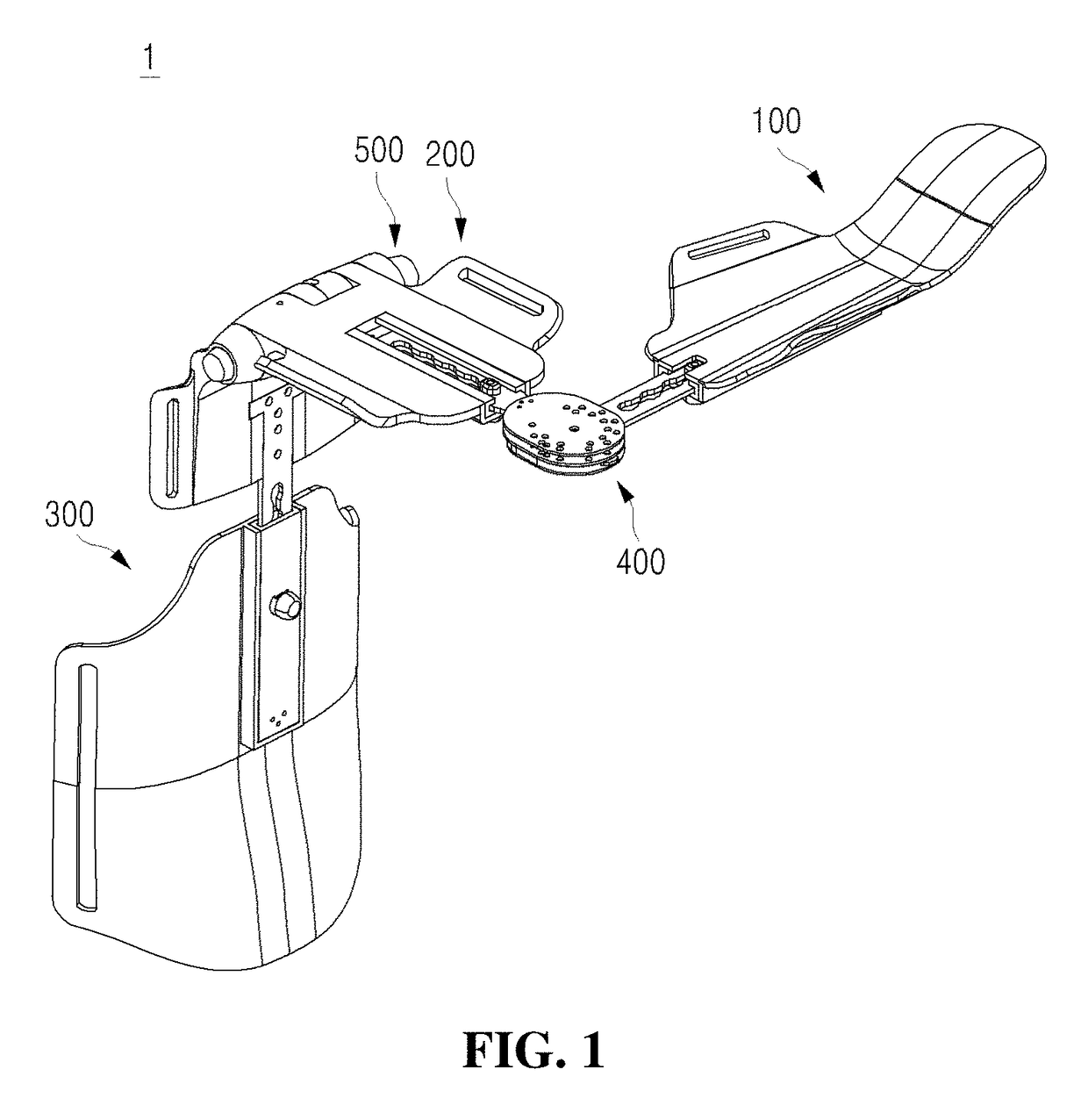
[0018]A shoulder brace 1 according to the present invention guarantees easy wearing, is adjustable in length depending on a wearer's body condition, and is intended to limit or adjust the motion range of the shoulder joint and elbow joint depending on a wearer's shoulder condition. Referring to FIG. 1, the shoulder brace 1 includes a forearm part 100 that is worn to surround and protect a medial portion of the forearm, an upper-arm part 200 that is worn to surround and protect a medial portion of the upper arm, a torso part 300 that is worn to surround and protect a side of the torso, an elbow-joint part 400 to which the forearm part and the upper-arm part are fastened, and a shoulder-joint part 500 to which the upper-arm part and the torso part are fastened.

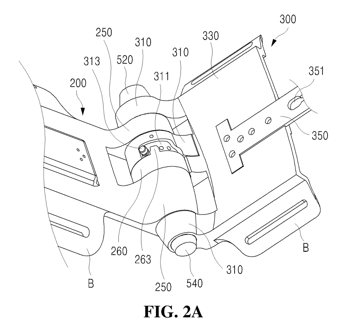
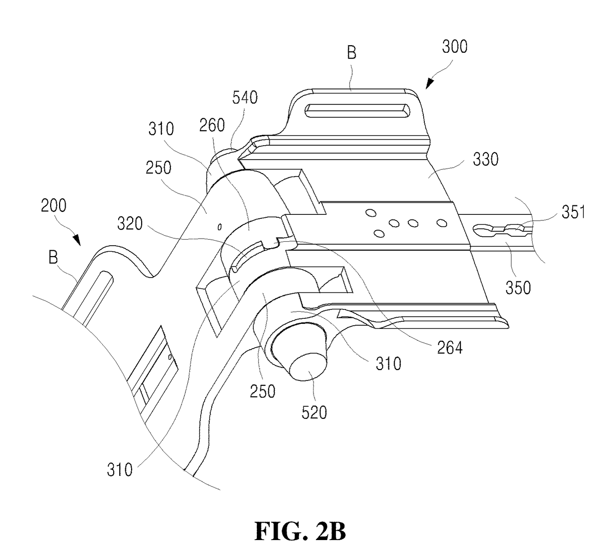
[0019]Referring to FIGS. 2A to 2C, the upper-arm part 200 surrounds and protects the medial porti...


PUM


Abstract

Provided is a shoulder brace having a forearm part, an upper-arm part, a torso part, an elbow-joint part, and a shoulder-joint part. The upper-arm part includes a rotary annulus to be coupled to an outside of the shoulder-joint part, the rotary annulus having line-shaped protrusions and grooves that are alternately formed along an inner circumference thereof. The shoulder-joint part includes a joint shaft, a push button provided on a first end thereof and coupled with the joint shaft, a locking ring coupled to a middle portion of the joint shaft and having line-shaped protrusions and grooves that are alternately formed along an outer circumference thereof, and a stopper formed on a second end thereof and providing space to allow the joint shaft to be movable when the push button is pushed, thus allowing a lock state to be released.

Description

CROSS-REFERENCE(S) TO RELATED APPLICATION[0001]This application claims priority of Korean Patent Application No. 10-2017-0116132, filed on 11 Sep. 2017, in the Korean Intellectual Property Office, which is hereby incorporated by reference in its entirety.BACKGROUND OF THE INVENTIONField of the Invention[0002]The present invention relates to a shoulder brace. More particularly, the invention relates to a shoulder brace, which guarantees easy wearing, is adjustable in length depending on the body condition of a wearer, and is capable of limiting or adjusting the motion ranges of the shoulder joint and the elbow joint depending on the condition of a wearer's shoulder.Description of the Related Art[0003]Generally, the shoulder joint is the joint between the shoulder bone and the humerus, and is also referred to as the shoulder in a narrow sense. The shoulder joint is the synovial joint made by the contact of the glenoid cavity of the shoulder bone with the humerus head, and is a key par...

Claims


Application Information

Patent Timeline
Patent Type & Authority Applications(United States)
IPC IPC(8): A61F5/01
CPCA61F5/013A61F2005/0158A61F2005/0155A61F5/3753A61F2005/0167A61F5/0102A61F2005/0181
Inventor KWARK, JEONG RANLEE, MI SEON
Owner COLUMBIA HEATHCARE CO LTD
Why Eureka
Try Eureka