Micromechanical rotational rate sensor system and corresponding production method

Active Publication Date: 2019-03-14
ROBERT BOSCH GMBH
View PDF12 Cites 8 Cited by
  • Summary
  • Abstract
  • Description
  • Claims
  • Application Information

AI Technical Summary

Benefits of technology

[0024]According to a further preferred development of the present invention, the first and/or second rotor device has one or more quadrature electrodes that are designed to interact with quadrature electrodes situated below them. This increases the drive precision.
[0025]According to a further preferred development of the present invention, the first acquisition device and the second acquisition device each have a pl

Problems solved by technology

This saves spac

Method used


Image

  • Micromechanical rotational rate sensor system and corresponding production method
  • Micromechanical rotational rate sensor system and corresponding production method
  • Micromechanical rotational rate sensor system and corresponding production method

Examples


Example

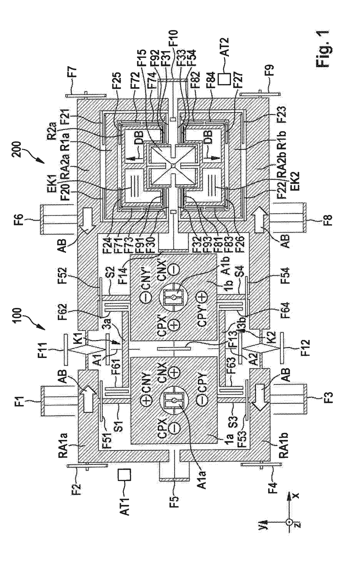
[0042]In the present first specific embodiment, first rotor device la and second rotor device 1b are realized as square plates, an associated first or second suspension device A1a, A1b being situated and anchored in a respective central opening.

[0043]First rotor device 1a can be tilted by the first external rate of rotation about the second axis (y axis) and by the second external rate of rotation about the third axis (x axis). Second rotor device 1b can be tilted by the first external rate of rotation about the second axis (y axis) and by the second external rate of rotation about the third axis (x axis) anti-parallel to first rotor device 1a.

[0044]First and second rotor device 1a, 1b are coupled, via a first spring device F13 as first coupling device, in such a way that a parallel tilting about the second axis (y axis) is suppressed, and an anti-parallel tilting about the second axis (y axis) is enabled, on the basis of an anisotropic spring constant.

[0045]Additionally provided i...

Example

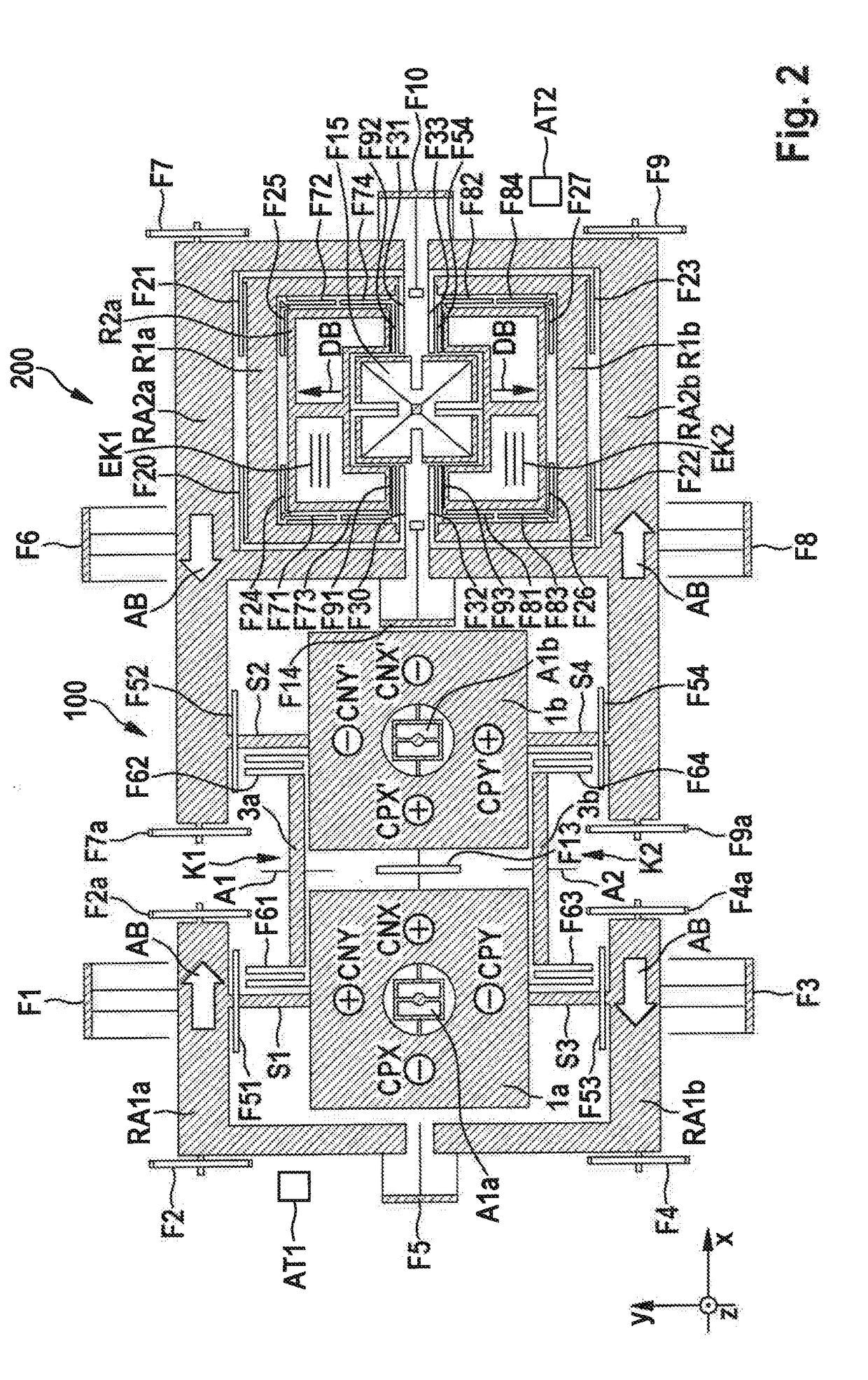
[0069]The second specific embodiment is realized analogously to the above-described first specific embodiment according to FIG. 1, and differs therefrom only in that first partial drive frame RA1a and third partial drive frame RA2a are not connected directly to one another, and second partial drive frame RA1b and fourth partial drive frame RA2b are also not directly connected to one another. First partial drive frame RA1a is connected to the substrate by a spring F2a, second partial drive frame RA1b is connected to the substrate via a spring F4a, third partial drive frame RA2a is connected to the substrate via a spring F1a, and fourth partial drive frame is connected to the substrate via a spring F9A.

[0070]An indirect connection of first drive frame RA1a, RA1b, and of second drive frame RA2a, RA2b is provided in the second specific embodiment via the above-described components F51 S1, F613a, F62 S2, F52 on the one side of first rotational rate acquisition device 100, and by the abov...

Example

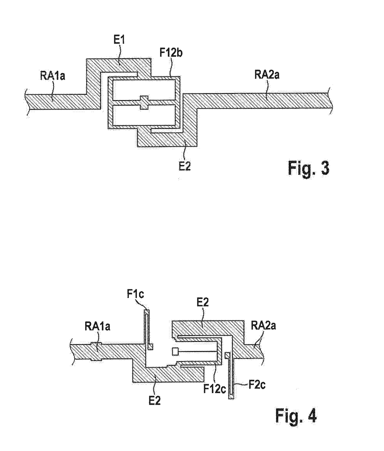
[0076]In the third specific embodiment, first partial drive frame RA1a′ and second partial drive frame RA1b′ are not realized with an angular shape, but rather are straight, and are not connected to one another, because spring F5 is omitted.

[0077]In particular, in this third specific embodiment only one drive is provided, here second drive AT2, already described above.

[0078]In addition, in all the specific embodiments first drive AT1 can be omitted where first drive frame RA1a, RA1b and second drive frame RA2a, RA2b are coupled to one another in linear fashion.

[0079]Further schematically shown is a quadrature electrode Q1 placed on first rotor device 1a, and which works together capacitively with a quadrature electrode Q2 situated under it in order to prevent movements outside the x-y plane by applying a corresponding voltage. Of course, such quadrature electrodes can be provided at other locations of the two rotor devices 1a, 1b in order to stabilize the operation of the first rota...


PUM


Abstract

A micromechanical rotational rate sensor system includes a first rotational rate sensor device that can be driven rotationally about a first axis in oscillating fashion for acquiring a first external rate of rotation about a second axis and a second external rate of rotation about a third axis, the first, second, and third axes being perpendicular to one another; and a second rotational rate sensor device, capable of being driven in linearly oscillating fashion along the second axis, for acquiring a third external rate of rotation about the first axis. The first rotational rate sensor device is connected to the second rotational rate sensor device via a drive frame device. The drive frame device has a first drive frame and a second drive frame that are capable of being driven in oscillating fashion by the drive device with opposite phase along the third axis.

Description

CROSS REFERENCE[0001]The present application claims the benefit under 35 U.S.C. § 119 of German Patent Application No. DE 102017216010.1 filed on Sep. 12, 2017, which is expressly incorporated herein by reference in its entirety.FIELD[0002]The present invention relates to a micromechanical rotational rate sensor system and to a corresponding production method.BACKGROUND INFORMATION[0003]Although any micromechanical components are also applicable, the present invention and its underlying problems are explained on the basis of micromechanical rotational rate sensor systems for motor vehicles.[0004]While the use of three-axis rotational rate sensors is standard in the area of consumer electronics, for automotive applications one-axis rotational rate sensors are typically used.[0005]For more complex automotive applications, such as inertial navigation for automated driving or for satellite-supported navigation, positional determination of camera-based or lidar-based environmental sensor...

Claims


Application Information

Patent Timeline
IPC IPC(8): G01C19/5762G01C19/5712
CPCG01C19/5762G01C19/5712G01P3/44G01C19/5747
Inventor BODE, NIELSLASSL, ANDREASKUHLMANN, BURKHARDLIEWALD, JAN-TIMOKUEHNEL, MATTHIASKUHLMANN, NILS FELIXPRUETZ, ODD-AXELDEGENFELD-SCHONBURG, PETERNEUL, REINHARD
Owner ROBERT BOSCH GMBH
Why Eureka
Try Eureka