Seat device for vehicle

Active Publication Date: 2019-03-21
TS TECH CO LTD
View PDF0 Cites 0 Cited by
  • Summary
  • Abstract
  • Description
  • Claims
  • Application Information

AI Technical Summary

Benefits of technology

[0041]In accordance with the first aspect of the present invention, since the dynamic damper is formed from the damper case that includes the first and second case halves joined together so that they can be separated from each other and defining the damper chamber in the interior, the weight housed in the damper chamber, and the elastic member disposed between the weight and the inner face of the damper chamber so as to allow vibration of the weight, it is possible to open the damper chamber by separating the damper case into the first and second case halves even after the dynamic damper has been assembled and to easily carry out adjustment and alteration of the damping characteristics of the dynamic damper by exchanging the weight and the elastic member in the interior of the damper chamber for ones having different characteristics.
[0042]Furthermore, since the damper case is provided with the mounting part mounted on the frames, it is possible to easily mount the damper case on the frame via the mounting part without using a special mounting implement such as a band.
[0043]In accordance with the second aspect of the present invention, since the plurality of pairs of elastic linking claws and linking holes, which snap fit together to thus join the first and second case halves, are formed on one and the other of the two case halves, it is possible to snap fit the plurality of pairs of elastic linking claws and linking holes merely by abutting the two case halves against each other, thus enabling the two case halves to be easily joined, and after joining it is also possible to separate the two case halves by subjecting the elastic linking claws to elastic deformation to thus disengage them from the linking holes.
[0044]In accordance with the third aspect of the pres

Problems solved by technology

In the dynamic damper in the seat device for a vehicle disclosed in Patent Document 1 above, after the weight and the elastic member are housed in the housing, the entirety of the housing is made into a unit so that it cannot come apart; once the dynamic damper is assembled, even if it is necessary to adjust or change the damping characteristics, it is impossible to repl

Method used


Image

  • Seat device for vehicle
  • Seat device for vehicle
  • Seat device for vehicle

Examples


first embodiment

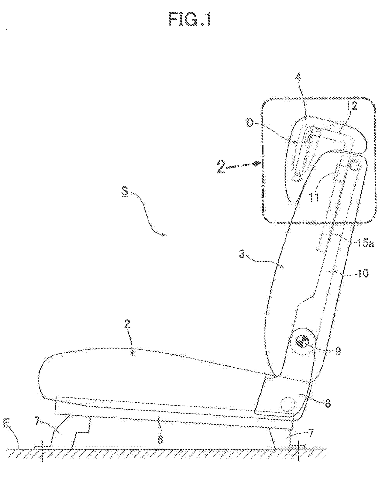
[0130]In FIG. 1, a seat S for an automobile is formed from a seat cushion 2, a seat back 3, and a headrest 4. The seat cushion 2 has a seat cushion frame 6 having formed in a lower part a plurality of support legs 7 and 7, and the support legs 7 and 7 are fixed to a floor F of the automobile.

[0131]A pair of left and right brackets 8, which project upwardly, are provided so as to be connected to a rear end part of the seat cushion frame 6, and a seat back frame 10 of the seat back 3 is linked to the brackets 8 via a pivot shaft 9 so that it can recline.

[0132]Furthermore, a pair of left and right support tubes 11 and 11 are fixedly provided on an upper end part of the seat back frame 10, and the headrest 4 is supported by these support tubes 11 and 11 so that it can be raised, lowered, and fixed.

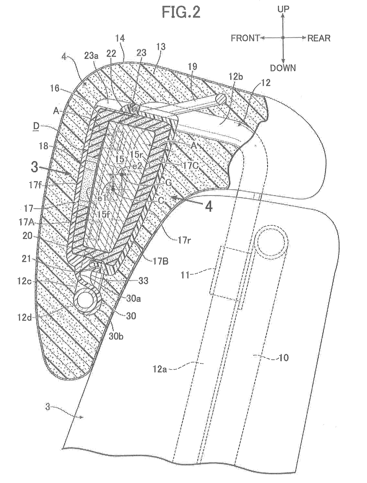
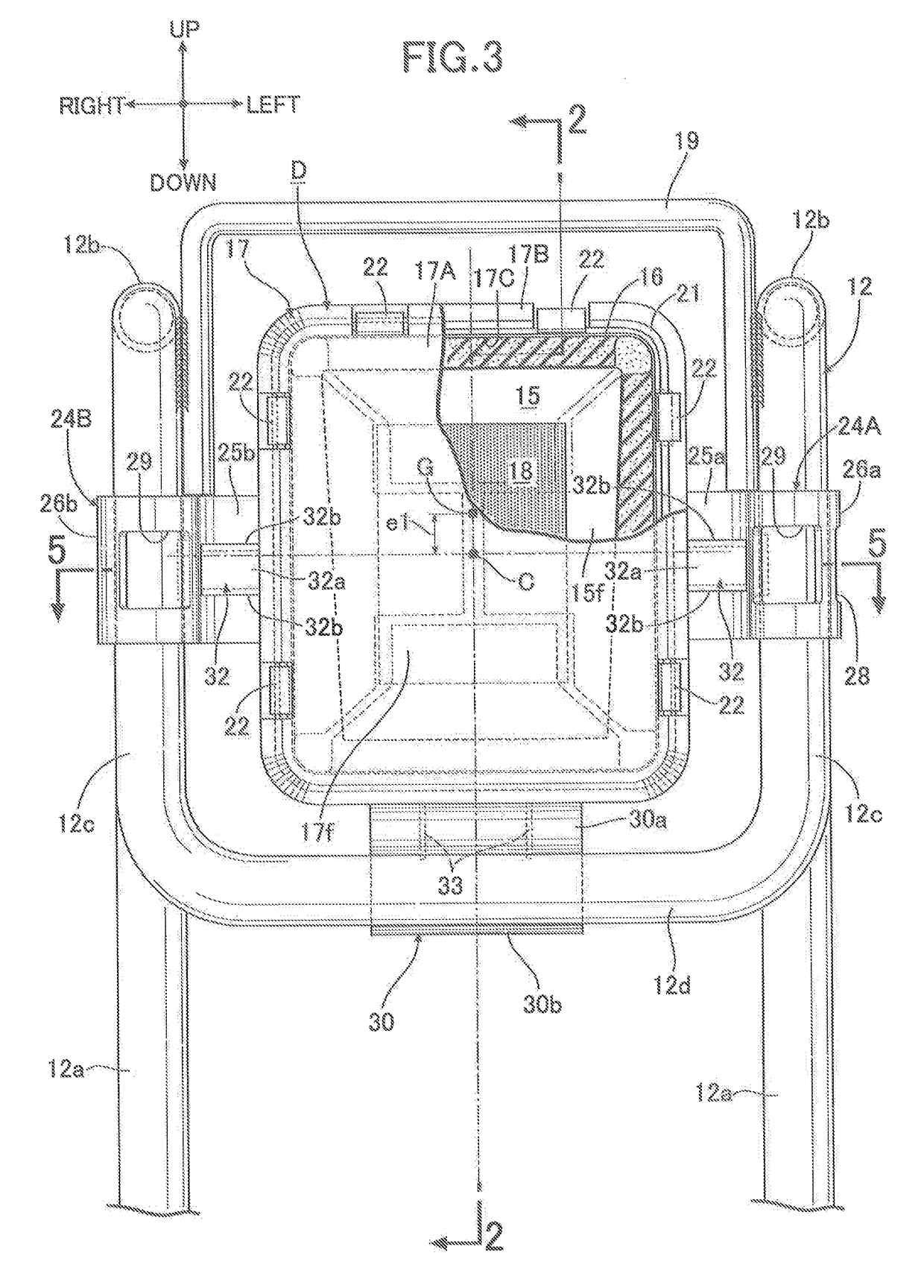
[0133]As shown in FIG. 2 to FIG. 6, the headrest 4 is formed into a teardrop shape, including a headrest frame 12, a urethane foam cushion member 13 supported on the frame, a surface skin or c...

second embodiment

[0169]In the second embodiment, three or more elastic support parts 24A to 24C supported on a headrest frame 12 are formed on a damper case 17 so as to be positioned at apexes of a polygon 34 surrounding the center of gravity G of a weight 15; specifically, the first to third elastic support parts 24A to 24C are formed on the damper case 17 so as to be disposed at the three apexes of an inverted triangle 34, and the weight 15 is formed so that the center of gravity G of the weight 15 is positioned in a region of the inverted triangle 34. The third elastic support part 24C is formed from an arm 25c and a major arc-shaped gripping claw 26c in basically the same manner as for the first and second elastic support parts 24A and 24B.

[0170]The first and second elastic support parts 24A and 24B are formed on a second case half 17B in the same manner as in the preceding embodiment and are snap fitted onto left and right front vertical frame members 12c and 12c of the headrest frame 12 from t...

third embodiment

[0174]In the third embodiment, the dynamic damper D of the first embodiment is mounted on left and right upper frame members 12b and 12b of a headrest frame 12. That is, first and second elastic support parts 24A and 24B of a damper case 17 are snap fitted onto the left and right upper frame members 12b and 12b from above, and a positioning support part 30 abuts against from below and engages with a cross member 46 linking rear end parts of the left and right upper frame members 12b and 12b. Since the arrangement is otherwise the same as that of the first embodiment, parts in FIG. 11 corresponding to those of the first embodiment are denoted by the same reference numerals and symbols, and duplication of the explanation is omitted.

[0175]In accordance with the third embodiment, it is possible, by utilizing effectively the space between the left and right upper frame members 12b and 12b for installing the dynamic damper D, to ensure that there is a sufficient thickness for a front part...


PUM


Abstract

A seat device for a vehicle includes a dynamic damper attached to a frame of a seat installed in the vehicle. The dynamic damper includes a damper case that is formed from separable first and second case halves, a weight that is housed in a damper chamber, and an elastic member that is disposed between the weight and the damper chamber so as to allow vibration of the weight. The damper case is provided with a plurality of mounting parts that are mounted on the frame, and the mounting parts comprise first and second mounting parts which are engaged with the frame at two left and right places as seen in a front view of the seat, and a third mounting part other than the first and second mounting parts which is provided between the first and second mounting parts.

Description

CROSS-REFERENCE TO RELATED APPLICATIONS[0001]This application is a continuation application of the U.S. patent application Ser. No. 15 / 902,256 (now U.S. Pat. No. 10,131,261 B2), filed on Feb. 22, 2018, which is a continuation application of the U.S. patent application Ser. No. 15 / 493,813 (now U.S. Pat. No. 9,937,829 B2), filed 21 Apr. 2017, which is a continuation application of the U.S. patent application Ser. No. 14 / 413,030 (now U.S. Pat. No. 9,746,048 B2), filed on Jan. 6, 2015, which is US National Phase of International Application No. PCT / JP2013 / 067103, filed Jun. 21, 2013, and which claims priority from five Japanese Patent Applications, i.e., Nos. 2012-152365 and 2012-152366 both filed on Jul. 6, 2012, No. 2012-166037 filed Jul. 26, 2012, No. 2012-170551 filed Jul. 31, 2012, and No. 2013-092947 filed Apr. 25, 2013. The entire contents of these prior applications are incorporated herein by reference.TECHNICAL FIELD[0002]The present invention relates to an improvement of a sea...

Claims


Application Information

Patent Timeline
IPC IPC(8): B60N2/80B60N2/68F16F7/108B60N2/90
CPCB60N2/68B60N2/682B60N2/80F16F7/108B60N2/891B60N2002/899
Inventor OKUBO, TAKUYA
Owner TS TECH CO LTD
Why Eureka
Try Eureka