
Synchronization signal block and control resource set multiplexing

a technology of control resource set and synchronization signal, applied in the field of wireless communication, can solve problems such as information not being transmitted

Active Publication Date: 2019-03-21
QUALCOMM INC
View PDF12 Cites 23 Cited by
  • Summary
  • Abstract
  • Description
  • Claims
  • Application Information

AI Technical Summary

Benefits of technology

The described techniques allow a base station to indicate to a user equipment the location of a coreset that includes control information. The user equipment can then identify the coreset based on the indication and the type of multiplexing used to mix the coreset with a signal block. This allows for synchronization signal block and control resource set multiplexing, and improves the efficiency of wireless communication.

Problems solved by technology

In such cases, however, the additional system information may not be transmitted in the SS block, and it may be challenging for the UE to identify the appropriate resources to monitor to receive the additional system information from the base station.

Method used


Image

  • Synchronization signal block and control resource set multiplexing
  • Synchronization signal block and control resource set multiplexing
  • Synchronization signal block and control resource set multiplexing

Examples


Embodiment Construction

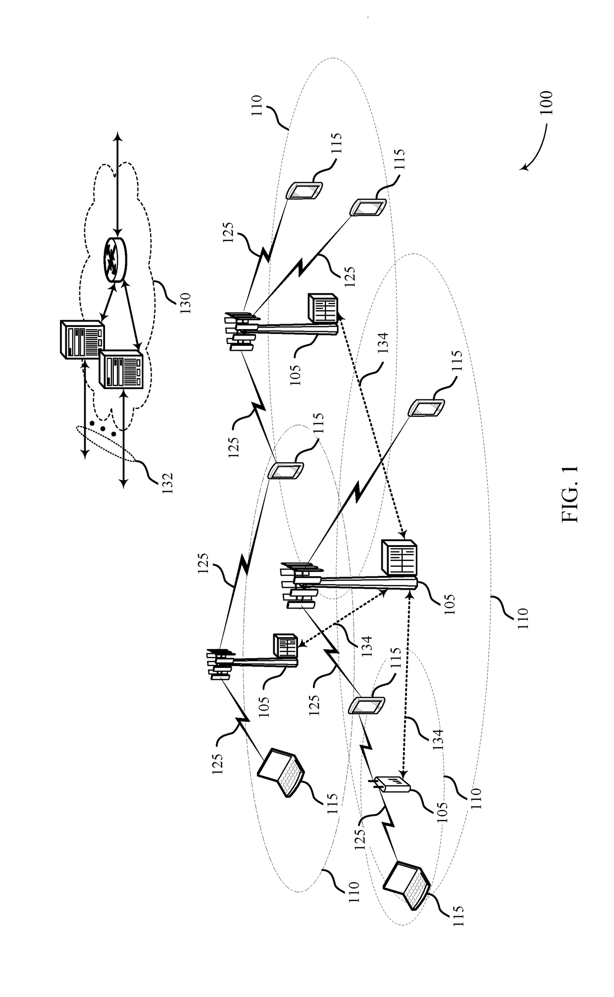
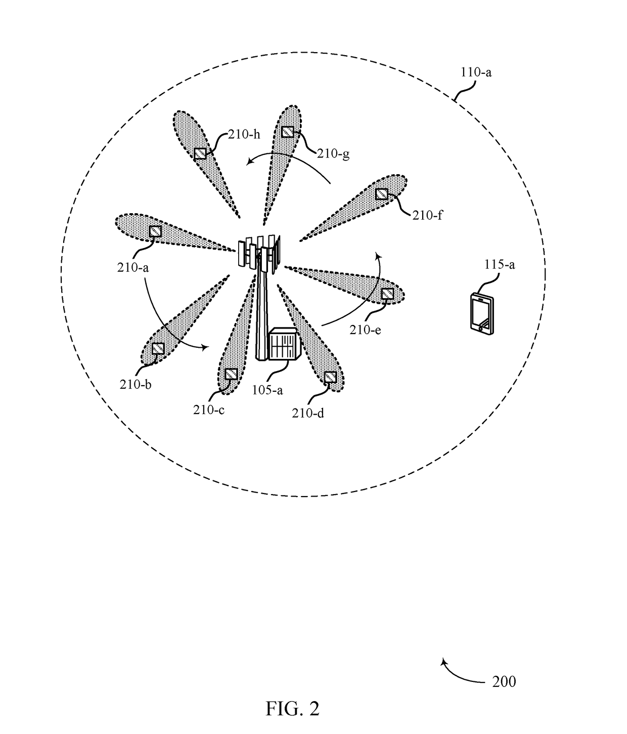
[0036]In some wireless communications systems (e.g., millimeter wave (mmW) systems), wireless devices (e.g., a base station and a user equipment (UE)) may utilize directional or beamformed transmissions (e.g., beams) to communicate with each other. In some cases, a base station may perform a beam sweep procedure to allow the base station and one or more UEs to identify appropriate beams for mmW communications. In such cases, the base station may also transmit synchronization signal (SS) blocks on each beam for one or more UEs to use to synchronize with the base station.

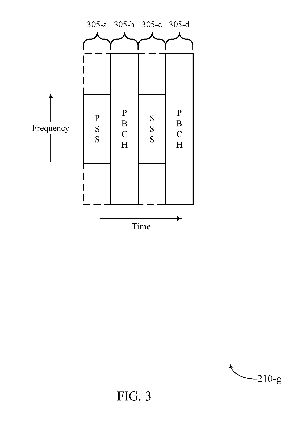
[0037]A UE may receive an SS block from the base station, and the UE may use the signals in the SS block to synchronize with the base station. For example, the UE may receive the synchronization signals included in the SS block, and the UE may, for example, identify timing information based on the synchronization signals that the UE may use to synchronize with the base station. The UE may also receive system informati...


PUM


Abstract

Methods, systems, and devices for synchronization signal (SS) block and control resource set (coreset) multiplexing are described. Generally, the described techniques allow a base station to indicate, to a user equipment (UE), the location of a coreset including control information that may be used by the UE. Specifically, a base station may transmit an indication of a coreset configuration and an indication of a type of multiplexing used to multiplex the coreset with an SS block in the SS block to a UE. Accordingly, the UE may receive the SS block, and the UE may determine the location of the coreset based on the coreset configuration and the indication of the type of multiplexing used to multiplex the coreset with the SS block. The UE may then process the control information included in the coreset to identify the location of a data channel including additional system information.

Description

CROSS REFERENCE[0001]The present Application for patent claims the benefit of U.S. Provisional Patent Application No. 62 / 559,368 by LY et al., entitled “SYNCHRONIZATION SIGNAL BLOCK AND CONTROL RESOURCE SET MULTIPLEXING,” filed Sep. 15, 2017, assigned to the assignee hereof, and expressly incorporated by reference herein.BACKGROUND[0002]The following relates generally to wireless communication and more specifically to synchronization signal (SS) block and control resource set (coreset) multiplexing.[0003]Wireless communications systems are widely deployed to provide various types of communication content such as voice, video, packet data, messaging, broadcast, and so on. These systems may be capable of supporting communication with multiple users by sharing the available system resources (e.g., time, frequency, and power). Examples of such multiple-access systems include fourth generation (4G) systems such as a Long Term Evolution (LTE) systems or LTE-Advanced (LTE-A) systems, and f...

Claims


Application Information

Patent Timeline
IPC IPC(8): H04J11/00H04L5/00H04B7/06H04W56/00H04W72/00H04L1/00
CPCH04J11/0069H04L5/0053H04B7/0695H04W56/001H04W72/005H04L1/0009H04L1/0038H04W72/1263H04W72/0446H04W72/0453H04W72/1273H04W72/23H04L5/0048H04L5/0091H04L5/0094H04W48/10H04L27/26025H04W72/30
Inventor LY, HUNG DINHLEE, HEECHOON
Owner QUALCOMM INC
Learn More