Water electrolysis system (SOEC) or fuel cell (SOFC) operating under pressure in a tight enclosure with improved regulation

a water electrolysis system and fuel cell technology, applied in the direction of electrolysis components, electrolysis processes, electrochemical generators, etc., can solve the problems of not being able to achieve the solution that could be envisioned, the difficulty of continuous operation, and the price of hydrogen production loss, etc., to achieve the effect of low risk of leakag

Active Publication Date: 2019-03-28
COMMISSARIAT A LENERGIE ATOMIQUE ET AUX ENERGIES ALTERNATIVES
View PDF0 Cites 4 Cited by
  • Summary
  • Abstract
  • Description
  • Claims
  • Application Information

AI Technical Summary

Benefits of technology

[0062]According to another variant of the invention, the system may furthermore comprise bypass valves VH,bypass, VO,bypass that are each arranged in parallel with the regulating valves VH, VO, respectively. These bypass valves allow operation at atmospheric pressure when they are opened. To this end, these bypass valves have a passage diameter of the same order of magnitude as that of the gas-flow lines so as to decrease head loss in their passages.
[0064]regulating, upstream of one of the chambers, the flow rate DH of wet gas so as to guarantee the electrochemical stability of the preset operating point;
[0072]A regulation on wet gas even has the advantage, for solid-oxide systems such as an HTE reactor or SOFC stack, of participating, by virtue of this expansion, in the cooling of the gas before it is sent to the condenser in which it will be cooled in order to remove most of the steam.

Problems solved by technology

Specifically, these seals, which are based on glass or glass-ceramic, and which ensure the seal-tightness of the stack with respect to the atmosphere, are fragile and are able to withstand only a slight positive pressure of about a few tens or a few hundred millibars.
In electrolysis mode, the major drawback of such a solution is that it comes at the price of a loss of some hydrogen production as some of the hydrogen is burned in the enclosure.
It is therefore not currently a solution that could be envisioned on an industrial scale, in electrolysis mode.
In electrolysis mode, one difficulty is also how to continuously and simultaneously obtain the same pressure (to within a few millibars) in the enclosure, in each anode chamber and in each cathode chamber, in order to best collect the produced gases.
However, another difficulty is due to the fact that the gas flowing through the cathode chambers contains a lot of steam, which may condense during its expansion to atmospheric pressure.
The solutions disclosed in this patent application and in this patent are however not applicable to solid-oxide systems in which the constraints are much more severe.
Another difficulty with the solution consisting in placing an HTE electrolyzer or an SOFC stack inside a pressurized enclosure is related to the fact that the stack comprises (anode and cathode) gas-flow chambers that intrinsically have a small volume with respect to that of the enclosure.
Pressure regulation is in this case difficult because variations in pressure inside the enclosure may be very slow with respect to those inside the chambers of the stack.
Thus, in case of a rapid increase in pressure in any one of the chambers of the stack, it will be very difficult to increase the pressure in the enclosure as rapidly.
This solution is constraining because it corresponds to multiplication of the volume of the pressurized enclosure by a factor of 3, and therefore the cost of the system is much higher.
In other words, in the prior art relating to high-temperature electrolyzers and fuel-cell stacks there is no system that provides a satisfactory solution to the regulation of the pressure of a wet gas in an operating range from atmospheric pressure to a few tens of bars.
However, this solution is one that was established and demonstrated for a specific experimental apparatus of small size, one of the risks of which was leakage from the metal seal of the pressurized enclosure.
Thus, although satisfactory and operational in a good number of configurations, this solution would require many measurements and regulations to be carried out if it were to be applied to the penalizing case in which the pressurized enclosure may have or is judged to have a relatively high risk of leakage to the outside.

Method used


Image

  • Water electrolysis system (SOEC) or fuel cell (SOFC) operating under pressure in a tight enclosure with improved regulation
  • Water electrolysis system (SOEC) or fuel cell (SOFC) operating under pressure in a tight enclosure with improved regulation
  • Water electrolysis system (SOEC) or fuel cell (SOFC) operating under pressure in a tight enclosure with improved regulation

Examples


Embodiment Construction

[0096]Other advantages and features of the invention will become more clearly apparent on reading the detailed description of examples of implementation of the invention, given by way of non-limiting illustration with reference to the following figures, in which:

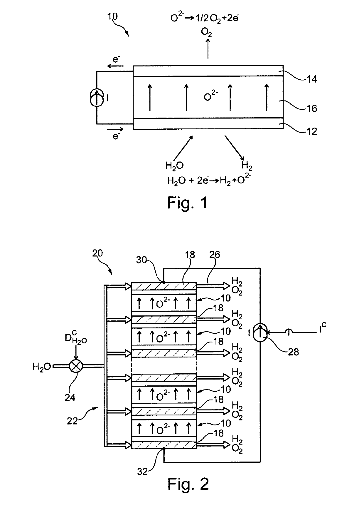
[0097]FIG. 1 is a schematic view of an elementary electrochemical cell of an HTSE electrolyzer;

[0098]FIG. 2 is a schematic view of a stack of cells according to FIG. 1;

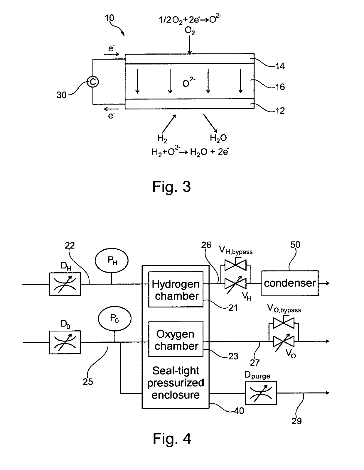
[0099]FIG. 3 is a schematic view of an electrochemical cell of an SOFC stack;

[0100]FIG. 4 is a schematic view of a system according to the invention comprising an HTE electrolyzer, the figure showing the flow-rate regulators and sensors required to regulate pressure in the flow chambers for steam and hydrogen and for oxygen and in the pressurized seal-tight enclosure that houses the chambers;

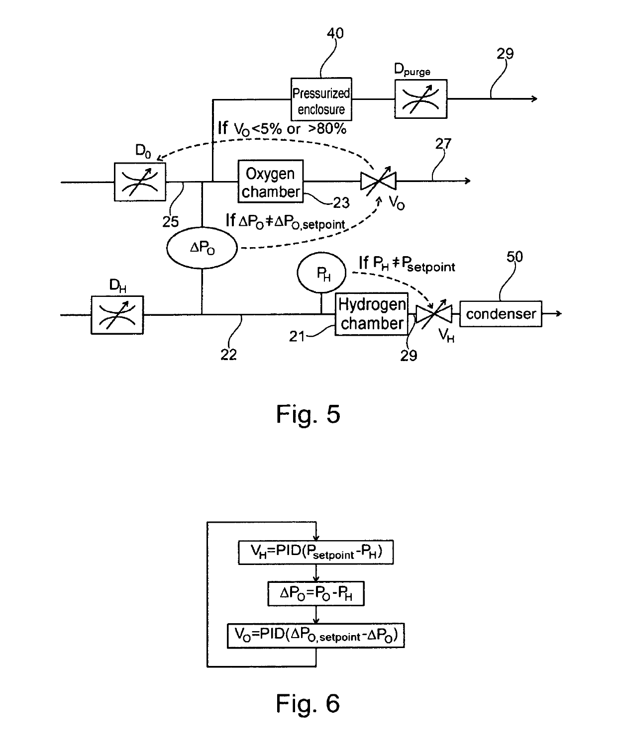
[0101]FIG. 5 is a schematic view of the flow-rate regulators and sensors with the automatic-control loops used to control the system according to FIG. 4 shown;

[0102]FIG. 6...


PUM

PropertyMeasurementUnit
operating pressure Pmaxaaaaaaaaaa
flow rate DHaaaaaaaaaa
pressureaaaaaaaaaa

Abstract

A system for regulating the pressure of a high-temperature electrolysis or co-electrolysis (HTE) reactor or a fuel cell (SOFC) operating under pressure. The operation of the system includes: regulating the DH wet gas flow upstream of one of the chambers so as to ensure the electrochemical stability of the predetermined operating point; regulating the DO gas flow upstream of the at least one second chamber so as to ensure gas scavenging in the at least one second chamber, and in the enclosure; regulating the flow of second gas circulating in the enclosure, downstream of the enclosure, so as to ensure the detection of leaks and safety in relation thereto and to prevent the formation of an explosive atmosphere; and controlling the pressure, by means of the regulation valves arranged downstream of the stack, on the gases, including the wet gas, which are also generally hot.

Description

TECHNICAL FIELD[0001]The present invention relates to the field of solid-oxide fuel-cell (SOFC) stacks and to the field of high-temperature electrolysis (HTE) of water (or HTSE, acronym for high-temperature steam electrolysis) in solid-oxide electrolysis cells (SOECs).[0002]The invention more particularly relates to the regulation of the pressure of an HTE electrolyzer system or of an SOFC stack operating under pressure.[0003]Although mainly described with reference to an application to high-temperature water electrolysis, the invention also applies to an SOFC stack.PRIOR ART[0004]The electrolysis of water is an electrolytic reaction that decomposes water into gaseous dioxygen and dihydrogen by means of an electrical current, according to the reaction:H2O→H2+½O2.[0005]It is advantageous to carry out the electrolysis of water at high temperature, typically between 600 and 950° C., as some of the energy required for the reaction may be supplied by heat, which is less expensive than el...

Claims


Application Information

Patent Timeline
Patent Type & Authority Applications(United States)
IPC IPC(8): C25B1/12C25B9/20H01M8/04089H01M8/04082H01M8/12
CPCC25B1/12C25B9/20H01M8/04104H01M8/04201H01M8/12C25B15/02H01M2008/1293H01M8/2425H01M8/2475H01M8/04089H01M8/04388H01M8/04395H01M8/04753H01M8/04761H01M8/04776H01M8/04783C25B1/00Y02E60/36Y02E60/50C25B1/04C25B9/05C25B9/73
Inventor PETITJEAN, MARIECHATROUX, ANDRE
Owner COMMISSARIAT A LENERGIE ATOMIQUE ET AUX ENERGIES ALTERNATIVES
Why Eureka
Try Eureka