Lighting device

a light source and light source technology, applied in the field of light source devices, can solve the problem of less uniform emission of light from the light source, and achieve the effect of high-level ligh

Active Publication Date: 2019-03-28
PANASONIC INTELLECTUAL PROPERTY MANAGEMENT CO LTD
View PDF0 Cites 9 Cited by
  • Summary
  • Abstract
  • Description
  • Claims
  • Application Information

AI Technical Summary

Benefits of technology

[0004]Typically, the longer the light guide is, the less uniform the emission of light from the light guide is. A lighting device that increases the uniformity of light emitted from the light guide is therefore in demand.
[0005]In view of this, the present disclosure has an object to provide a lighting device that can emit highly uniform light.
[0007]With the present disclosure, it is possible to emit highly uniform light.

Problems solved by technology

Typically, the longer the light guide is, the less uniform the emission of light from the light guide is.

Method used


Image

  • Lighting device
  • Lighting device
  • Lighting device

Examples


embodiment 1

Variation of Embodiment 1

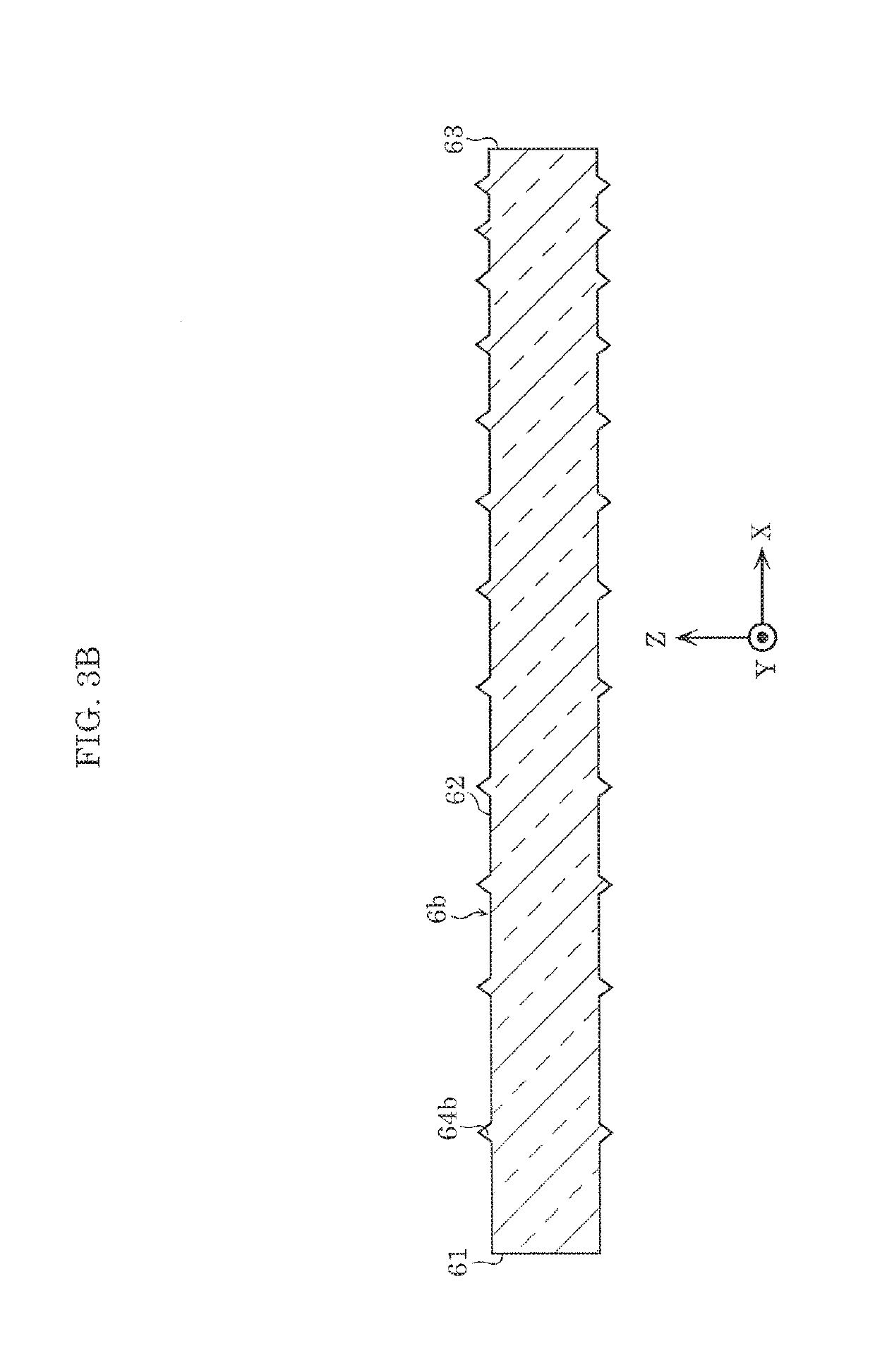
[0071]FIG. 4A illustrates a cross-sectional view of linear light guide 6 in linear lighting device 1 according to a variation of Embodiment 1.

[0072]In this variation, recesses 164 differ from the recesses according to Embodiment 1 in that they vary in depth. Moreover, unless otherwise stated, linear lighting device 1 according to this variation has the same configuration as Embodiment 1. Accordingly, like elements share like reference signs in the drawings, and repeated detailed description of those elements are omitted.

[0073]As illustrated in. FIG. 4A, a plurality of recesses 164 are formed in first emission surface 62 of linear light guide 6. Recesses 164 or the protrusions of the uneven surface structure gradually increase in depth or height, respectively, with distance from entrance surface 61. In this embodiment, recesses 164 are used. More specifically, each recess 164 has the same diameter, but the depth of recesses 164 gradually increases with distan...

embodiment 2

Variation of Embodiment 2

[0103]FIG. 8A illustrates a cross-sectional view of linear light guide 306 in linear lighting device 201 according to a variation of Embodiment 2.

[0104]In this variation, recesses 164 or protrusions differ from Embodiment 1 in that they vary in depth or height, respectively. Moreover, unless otherwise stated, linear lighting device 201 according to this variation has the same configuration as Embodiment 2. Accordingly, like elements share like reference signs in the drawings, and repeated detailed description of those elements are omitted.

[0105]As illustrated in FIG. 8A, a plurality of recesses 164 are formed in emission surface 362 of linear light guide 306. Recesses 164 or protrusions in the uneven surface structure gradually increase in depth or height, respectively, with distance from first entrance surface 61a to the central region of linear light guide 306 and from second entrance surface 63a to the central region of linear light guide 306. Each recess...


PUM


Abstract

A lighting device includes a laser light source that emits laser light, a wavelength converter that converts a wavelength of the laser light and emits wavelength-converted light, and a linear light guide that is elongated and guides the wavelength-converted light emitted by the wavelength converter and introduced through a longitudinal end surface. The linear light guide includes a lateral surface that emits the wavelength-converted light guided by the linear light guide. A proportion of the wavelength-converted light emitted by the lateral surface gradually increases with an increase in optical path length in the linear light guide.

Description

CROSS REFERENCE TO RELATED APPLICATION[0001]This application claims the benefit of priority of Japanese Patent Application Number 2017-184011 filed on Sep. 25, 2017, the entire content of which is hereby incorporated by reference.BACKGROUND1. Technical Field[0002]The present disclosure relates to a lighting device.2. Description of the Related Art[0003]A conventional vehicle lamp that includes a laser light source and a light guide that transmits the laser light emitted by the laser light source is known (for example, see Japanese Unexamined Patent Application Publication No. 2014-17060).SUMMARY[0004]Typically, the longer the light guide is, the less uniform the emission of light from the light guide is. A lighting device that increases the uniformity of light emitted from the light guide is therefore in demand.[0005]In view of this, the present disclosure has an object to provide a lighting device that can emit highly uniform light.[0006]In order to achieve the object described sho...

Claims


Application Information

Patent Timeline
Patent Type & Authority Applications(United States)
IPC IPC(8): H01L33/50F21V8/00
CPCH01L33/50G02B6/0026G02B6/0071G02B6/0031G02B6/0006G02B6/001H01S5/02208H01S5/32341H01S5/0087H01S5/02251
Inventor YAMAE, KAZUYUKI
Owner PANASONIC INTELLECTUAL PROPERTY MANAGEMENT CO LTD
Why Eureka
Try Eureka