Method for managing radio resources in communication system and apparatus for the same

a technology of communication system and radio resource, applied in diversity/multi-antenna system, synchronisation arrangement, wireless communication, etc., can solve the problems of radio link configuration failure, management cost, or the like of the integrated communication system, and increase the initial investment cost, so as to improve the performance of communication system and efficiently control the mobility of terminals

Active Publication Date: 2019-03-28
ELECTRONICS & TELECOMM RES INST
View PDF6 Cites 47 Cited by
  • Summary
  • Abstract
  • Description
  • Claims
  • Application Information

AI Technical Summary

Benefits of technology

[0007]Accordingly, embodiments of the present disclosure provide beam management methods for ensuring mobility of terminals in a communication system.
[0028]According to the embodiments of the present disclosure, one or more beams can be configured between the base station and the terminal, and the terminal may perform communications with the base station using the configured beams. When a beam problem is detected during the communications between the base station and the terminal, the terminal can perform a recovery operation on the beam in which the beam problem is detected. When the recovery operation fails, the terminal can perform a reconfiguration operation on another beam of the base station. When the reconfiguration operation fails, the terminal can perform a re-establishment operation of a radio link with another base station. Through the above-described beam management operation, a communication service can be seamlessly provided to the terminal, and mobility of the terminal can be efficiently controlled. Therefore, the performance of the communication system can be improved.

Problems solved by technology

In the integrated using a wired backhaul link, in which case an initial investment cost, management cost, or the like of the integrated communication system may be increased.
When a plurality of beams are configured between the first base station and the terminal and all of reconfiguration operations on the plurality of beams fail, the radio link configuration failure may be determined.

Method used


Image

  • Method for managing radio resources in communication system and apparatus for the same
  • Method for managing radio resources in communication system and apparatus for the same
  • Method for managing radio resources in communication system and apparatus for the same

Examples


first embodiment

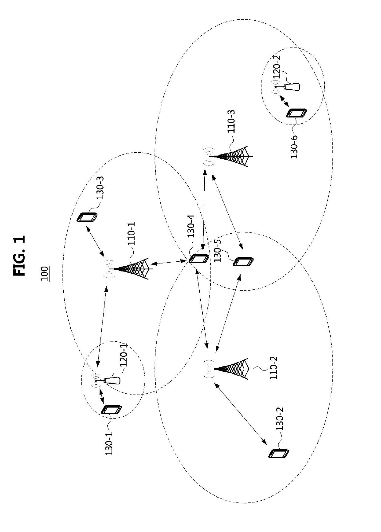
[0045]FIG. 1 is a conceptual diagram illustrating a communication system.

[0046]Referring to FIG. 1, a communication system 100 may comprise a plurality of communication nodes 110-1, 110-2, 110-3, 120-1, 120-2, 130-1, 130-2, 130-3, 130-4, 130-5, and 130-6. Also, the communication system 100 may further include a core network. The core network supporting 4G communication (e.g., long term evolution (LTE) and LTE-advanced (LTE-A)) may comprise a serving gateway (S-GW), a packet data network (PDN) gateway (P-GW), a mobility management entity (MME), and the like. The core network supporting 5G communication (e.g., new radio (NR)) may comprise a user plane function (UPF), an access and mobility management function (AMF), and the like. The S-GW may correspond to the UPF, and the MME may correspond to the AMF. Thus, in the embodiments described below, the S-GW may mean the UPF, the MME may mean the AMF, and the S-GW / MME may mean the UPF / AMF.

[0047]The plurality of communication nodes may supp...

second embodiment

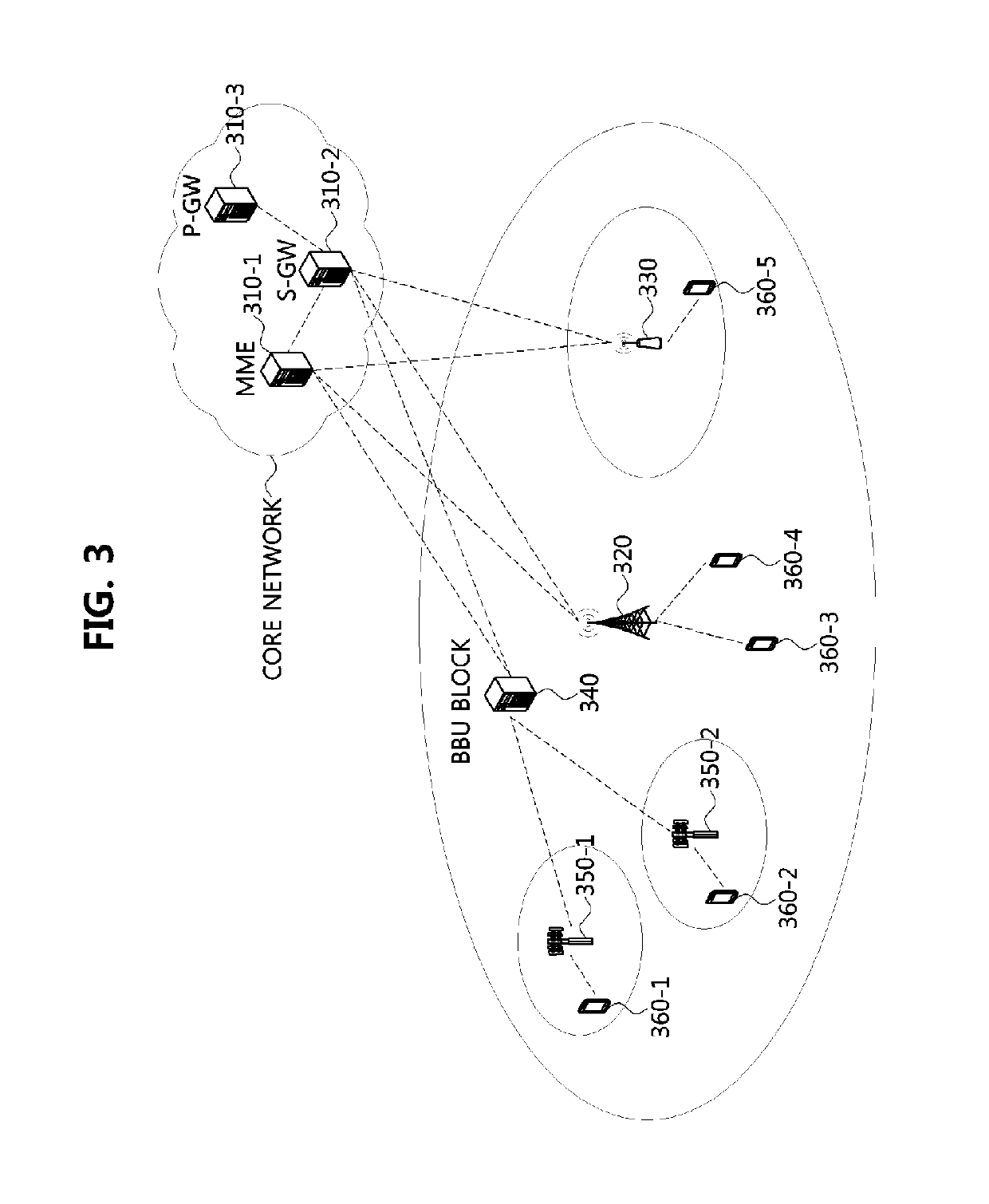
[0058]FIG. 3 is a conceptual diagram illustrating a communication system.

[0059]Referring to FIG. 3, a communication system may include a core network and an access network. The core network supporting the 4G communications may include an MME 310-1, an S-GW 310-2, a P-GW 310-3, and the like. The core network supporting the 5G communications may include AMF, UPF, or the like. The access network may include a macro base station 320, a small base station 330, TRPs 350-1 and 350-2, terminals 360-1, 360-2, 360-3, 360-4, and 360-5, and the like. The macro base station 320 or the small base station 330 may be connected with an end node of the core network via a wired backhaul. The TRPs 350-1 and 350-2 may support the remote radio transmission and reception function among all the functions according to the communication protocol, and the baseband processing functions for the TRPs 350-1 and 350-2 may be performed by the BBU block 340. The BBU block 340 may belong to the access network or the ...

case 1

[0213]The terminal may perform the beam reconfiguration operation (e.g., beam monitoring operation) after the beam recovery operation has failed (e.g., after the beam failure has been determined), and the beam selected by the beam reconfiguration operation may be one of the following beams.[0214] The same beam as the previous serving beam (e.g., the beam in which a beam failure is determined in the beam recovery step)[0215]Case 2: Another beam of the serving base station (e.g., the base station to which the beam in which a beam failure is determined in the beam recovery step belongs)[0216]Case 3: Abeam of a base station other than the serving base station (e.g., the base station to which the beam in which a beam failure is determined in the beam recovery step belongs)

[0217]In Case 1, the terminal may perform the operations specified in the ‘recovery operation of the same beam’ described above.

[0218]In Case 2, the control message used to change the Resource-Config information may be ...


PUM


Abstract

A beam management method, performed by a terminal in a communication system, includes receiving a control message including at least one parameter used for beam management from a first base station; performing a monitoring operation on a first beam configured between the first base station and the terminal based on the at least one parameter; detecting a beam problem in the first beam based on the monitoring operation; and in response to determination that the beam problem is detected in the first beam, performing a recovery operation on the first beam.

Description

CROSS-REFERENCE TO RELATED APPLICATIONS[0001]This application claims priorities to Korean Patent Applications No. 10-2017-0124876 filed on Sep. 27, 2017, No. 10-2017-0147569 filed on Nov. 7, 2017, No. 10-2018-0017157 filed on Feb. 12, 2018, No. 10-2018-0084630 filed on Jul. 20, 2018, No. 10-2018-0091430 filed on Aug. 6, 2018, and No. 10-2018-0103454 filed on Aug. 31, 2018 in the Korean Intellectual Property Office (KIPO), the entire contents of which are hereby incorporated by reference.BACKGROUND1. Technical Field[0002]The present disclosure relates to a technique for managing radio resources, and more particularly, to a beam management technique for ensuring terminal mobility.2. Description of Related Art[0003]A communication system (hereinafter, an ‘integrated communication system’) using a higher frequency band (e.g., a frequency band of 6 GHz or higher) than a frequency band (e.g., a frequency band lower below 6 GHz) of a long term evolution (LTE) based communication system (or...

Claims


Application Information

Patent Timeline
Patent Type & Authority Applications(United States)
IPC IPC(8): H04W24/04H04W76/27H04W72/04H04W24/10H04L5/00H04B7/06H04W56/00H04W76/28
CPCH04W24/04H04W76/27H04W72/046H04W24/10H04L5/0048H04B7/0695H04W56/001H04W76/28H04B7/0617H04W80/02H04L5/0053H04B7/0404
Inventor KIM, JAE HEUNG
Owner ELECTRONICS & TELECOMM RES INST
Why Eureka
Try Eureka