
Rotor of Rotating Electric Machine and Manufacturing Method of the Same

Active Publication Date: 2019-04-11
TOYOTA JIDOSHA KK
View PDF2 Cites 6 Cited by
  • Summary
  • Abstract
  • Description
  • Claims
  • Application Information

AI Technical Summary

Benefits of technology

This patent aims to reduce the eddy current loss in a rotating electric machine's rotor by reducing or eliminating the parts where magnets and the rotor core are in contact with each other without electric insulating films. The current configuration described in the patent has a lot of room for improvement in reducing the film's usage and cost. The present disclosure proposes a solution to these issues by reducing eddy current loss, cost, and positioning each magnet in its hole in a stable manner.

Problems solved by technology

In the meantime, if the electric insulating films are omitted from the entire surfaces of each magnet, it is difficult to stably restrict the position of each magnet in each magnet hole.

Method used


Image

  • Rotor of Rotating Electric Machine and Manufacturing Method of the Same
  • Rotor of Rotating Electric Machine and Manufacturing Method of the Same
  • Rotor of Rotating Electric Machine and Manufacturing Method of the Same

Examples


Embodiment Construction

[0027]Hereinafter, an embodiment of the present disclosure will be described with reference to the drawings. In the following description, shapes, materials, and the numbers of components are merely exemplified for explanation, and may be appropriately changed in accordance with the specifications of a rotor of a rotating electric machine. Hereinafter, equivalent components will be denoted by the same reference numerals in all the following drawings. In explanation of the present description, previously-mentioned reference numerals will be used if necessary.

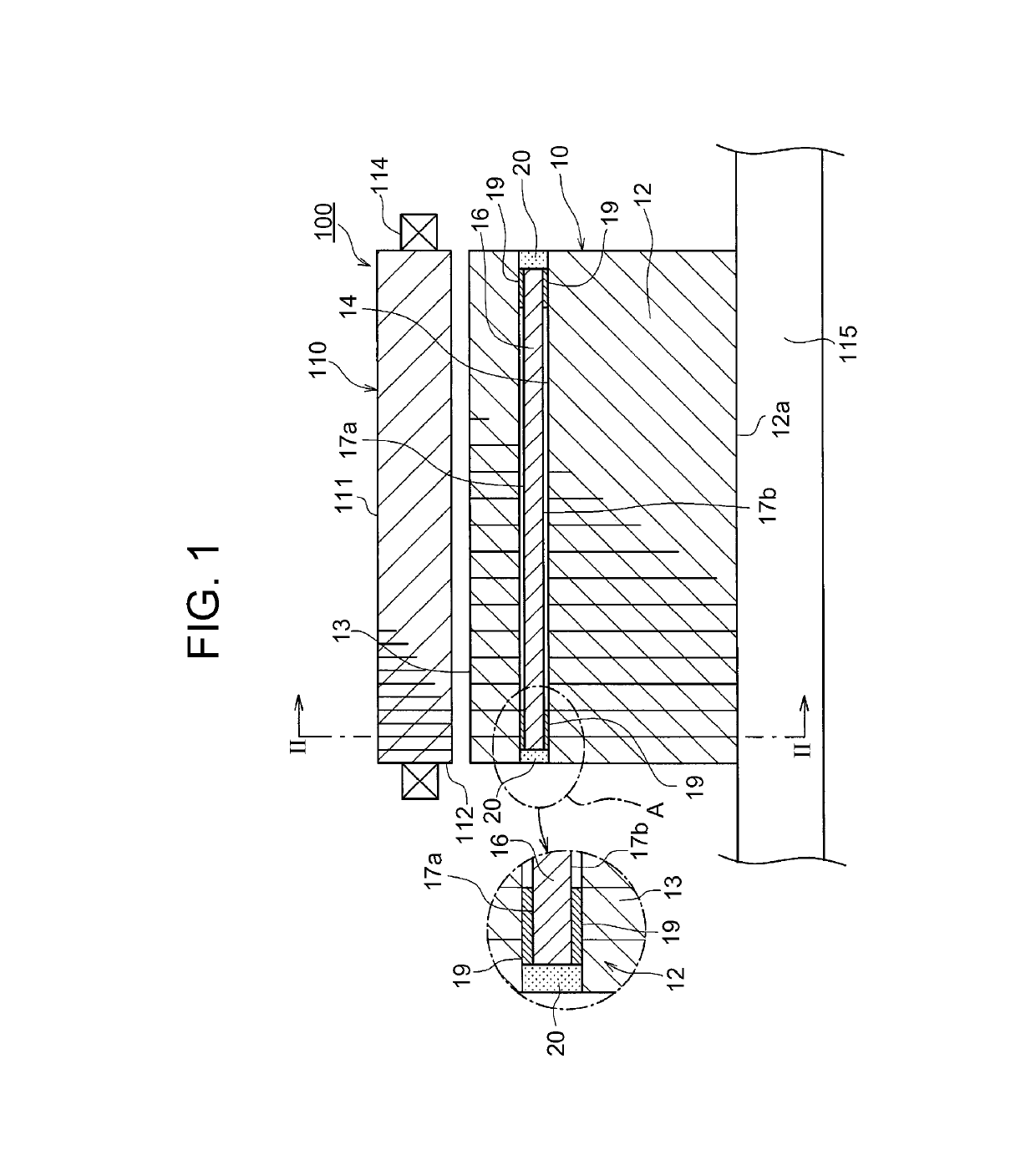
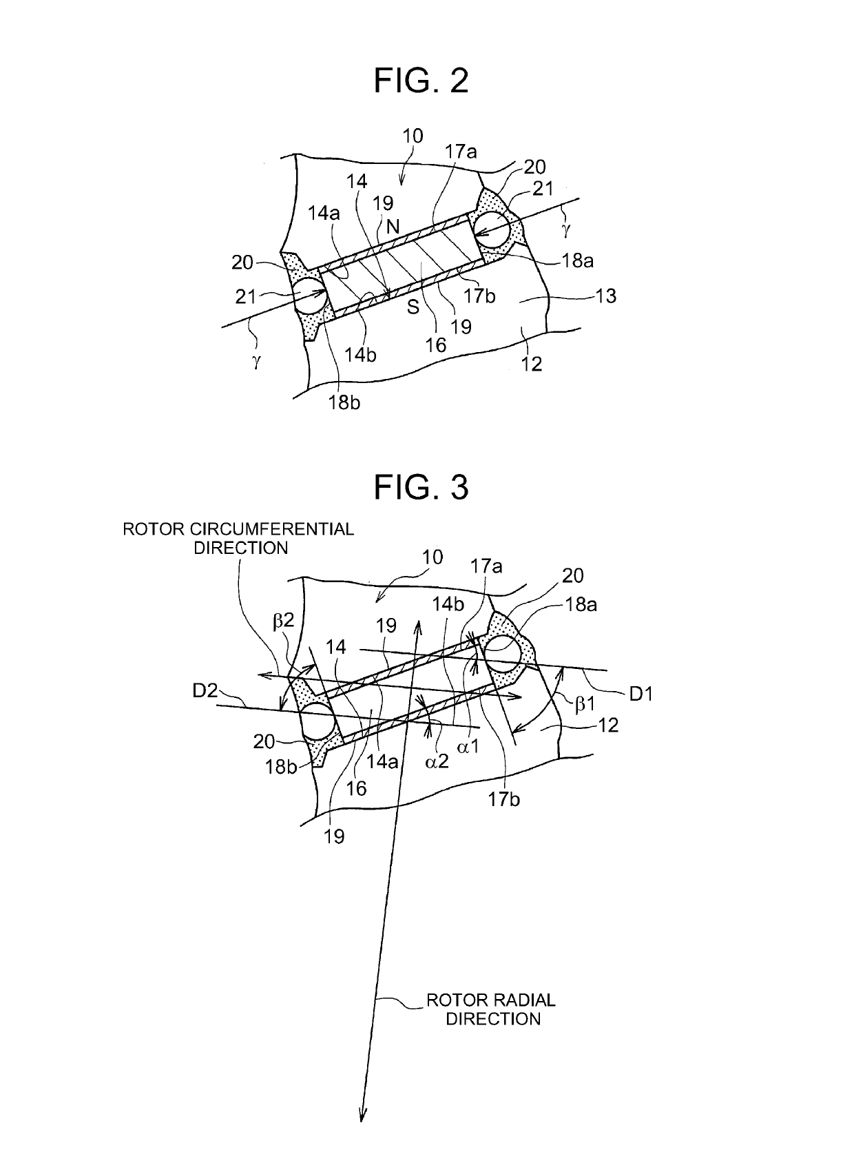
[0028]FIG. 1 shows a half sectional view of a rotating electric machine 100 including a rotor of a rotating electric machine 10 of the embodiment, and also shows an enlarged view of a part A thereof. FIG. 2 is a sectional view taken along line II-II in FIG. 1 in a part in the circumferential direction of the rotor of the rotating electric machine 10. Hereinafter, the rotor of the rotating electric machine 10 might also be referre...


PUM


Abstract

A rotor for a rotating electric machine includes: a rotor core having magnet holes; magnets inserted in the magnet holes of the rotor core. Each of the magnets includes two first surfaces respectively facing outward and inward of the rotor radial direction, and two second surfaces respectively facing one side and the other side of the rotor circumferential direction. Both ends in the rotor axial direction of at least one first surface of the two first surfaces are covered with electric insulating films, and a lateral surface region between both ends of the one first surface that are covered with the electric insulating films, and the two second surfaces are covered with no electric insulating films.

Description

INCORPORATION BY REFERENCE[0001]The disclosure of Japanese Patent Application No. 2017-195270 filed on Oct. 5, 2017 including the specification, drawings and abstract is incorporated herein by reference in its entirety.BACKGROUND1. Technical Field[0002]The present disclosure relates to a rotor of a rotating electric machine, having magnets inserted in magnet holes that are formed in a rotor core, and to a manufacturing method of the same.2. Description of Related Art[0003]In a rotor of a rotating electric machine included in the rotating electric machine, there is known a configuration in which magnets are inserted into magnet holes formed in a rotor core so as to be fixed to the rotor core.[0004]Japanese Patent Application Publication No. 2015-23620 (JP 2015-23620 A) describes a configuration in which each magnet is inserted into each magnet hole formed in a rotor core, and entire surfaces parallel to the rotor axial direction at both ends in the rotor axial direction of each magne...

Claims


Application Information

Patent Timeline
IPC IPC(8): H02K15/12H02K15/10H02K1/27H02K15/03
CPCH02K15/12H02K15/10H02K1/276H02K15/03H02K1/28H02K1/27H02K1/04H02K11/01
Inventor GANGI, SUGURUHATTORI, HIROYUKISANO, SHINYANODA, KEN
Owner TOYOTA JIDOSHA KK
Learn More