Device for gripping and inserting an insert element

a technology of insert elements and devices, which is applied in the field of devices for inserting insert elements, can solve the problems of difficult removal, difficult to grasp, and difficult to remove, and achieve the effects of avoiding cracks or breakages, avoiding deterioration, and precise orientation

Active Publication Date: 2019-04-18
XNOV IP
View PDF3 Cites 1 Cited by
  • Summary
  • Abstract
  • Description
  • Claims
  • Application Information

AI Technical Summary

Benefits of technology

[0005]The present invention proposes overcoming the disadvantages of the prior art by proposing an insertion device which makes it possible to achieve the impaction of the insert into the cup with a very precise orientation relative to the insert and the cup, thus largely avoiding its deterioration over the long term, in particular avoiding cracks or breakages, and thus guaranteeing a long lifetime for the cup in the hip.
[0013]In this way an insertion device is obtained for insertion by impaction which makes it possible to perform said insertion in a particularly reliable and simple manner, by reducing to a very large degree the risk of “off-centre” insertion, which is a potential source of tearing or breaking of the cup once it has been placed into the cotyl. Whatever the angle of the force of impaction relative to the insert, i.e. the orientation of the rod relative to the insert, the latter, held by the insertion device with the possibility of pivoting, is always positioned perfectly relative to the cup, regardless of the orientation of the rod relative to the cup, such that the surgeon no longer needs, as in the prior art, to ensure that the rod is aligned perfectly perpendicularly to the plane of the base of the cup during the insertion.
[0020]In this way a free orientation of the insert is achieved.
[0022]According to data and / or experience, it is also possible to adjust the power of the shock to optimise the blow given to the insert for the insertion thereof, thus avoiding variations in the power provided by the practitioner and / or his form on the day which are likely to involve either the cracking or breaking of the insert or the cup, or an incomplete insertion of the insert into the cup.
[0025]According to a preferred embodiment, it is possible to provide means for locking the piston in a loaded position in which the spring is compressed and means, in particular in the form of a trigger, designed to release the piston, the release of the piston involving its instantaneous displacement by means of the decompression of the spring and its pulse action on the rod imparting to the latter a predetermined level of shock.

Problems solved by technology

Insertion devices are already known that comprise a rod, an impaction head fixed to the end of the rod and designed to come into contact with the insert and gripping means designed for temporarily holding the insert to the insertion device when the impaction head is in contact with the insert, the latter being then adjusted by force to the cup by means of a shock or impaction applied to the rod by the surgeon to secure it in such a way that it is difficult, almost impossible, to remove.
Said devices of the prior art are complicated to use and do not guarantee a reliable impaction force in the right direction.
It is often the case that either the insert is misaligned in relation to the cup prior to its impaction, or the axis in which the impaction is performed is not set accurately in a direction suitable for joining the insert and the cup perfectly.
As a result the insert could be fitted badly in the cup, which over the long term may lead to breaking and associated complications for the patient (new operation for removing the defective cup, which is often shattered, and refitting a cup).

Method used


Image

  • Device for gripping and inserting an insert element
  • Device for gripping and inserting an insert element
  • Device for gripping and inserting an insert element

Examples


Embodiment Construction

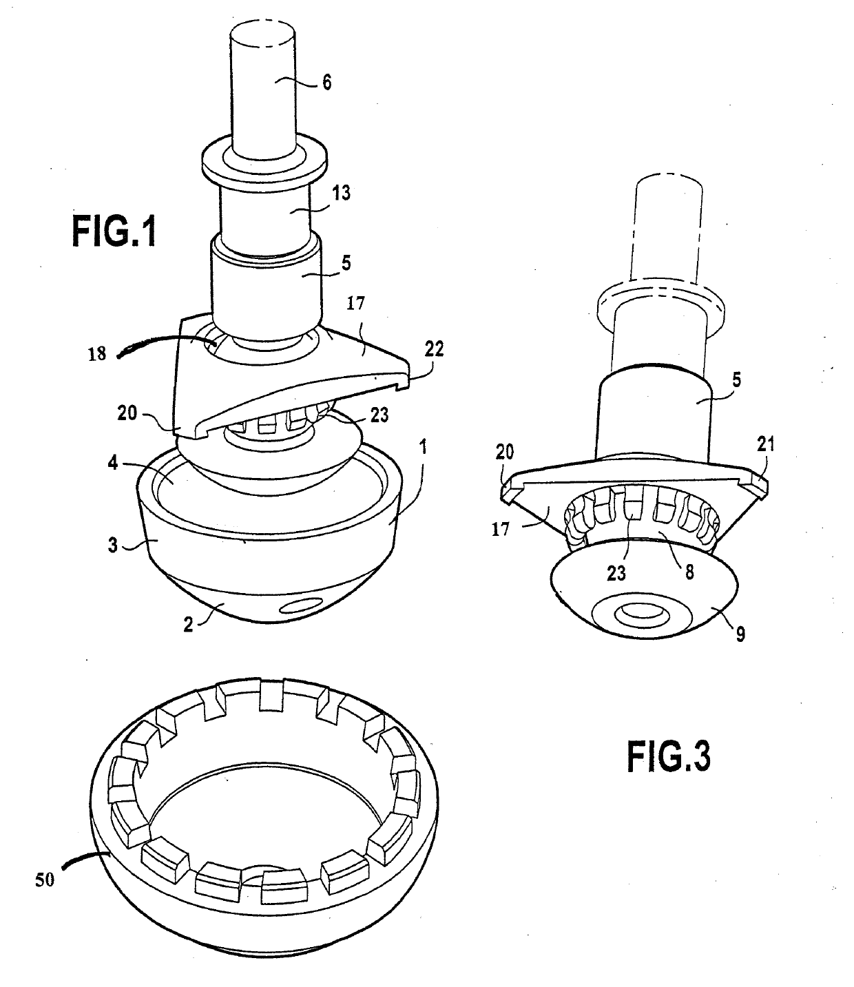
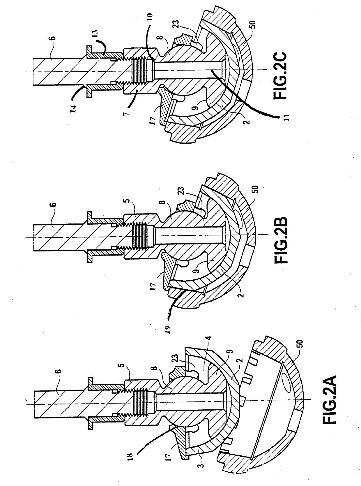
[0035]FIG. 1 is a perspective view of an insertion device according to an embodiment of the invention of an insert 1 made of ceramic material in a cup 50. The insert 1 made of ceramic material is formed by a ceramic body, in particular made of alumina ceramic material, with an exterior surface in the form of a spherical cap 2 terminated by a part 3 of the upper or proximal edge with a slightly truncated cone shape. The insert is hollow and comprises an inner cavity 4 the wall of which has a hemispherical form. In particular, the shaped cone of the truncated cone part 3 of the edge of the outer surface of the insert forms an angle of about 3 to 5° relative to the vertical axis of symmetry of the insert made of ceramic material.

[0036]The insertion device is formed by a circular cylindrical rod 6 to which an impaction end piece 5 has been adapted at its distal end. The end piece 5 comprises a tubular proximal section 7 which is tapped to receive the threaded end of the rod 6 therein, t...


PUM


Abstract

A device for a cup to be received in the cotyl of a hip. The device includes an insert, a gripping means for gripping the insert, a rod for imparting shock, and an impaction head having a surface in contact with a portion of the insert. The rod for imparting shock is designed to be held by a surgeon and is used for the application of an impaction shock to the insert when held by the gripping means opposite the cup to be introduced into the cotyl of a hip. The impaction head having a surface in contact with a portion of said insert and the rod are connected to one another so as form a head and rod assembly joined in rotation.The head and rod assembly is mounted pivotably at a pivot point in relation to the gripping means.

Description

CROSS-REFERENCE TO RELATED APPLICATIONS[0001]This application is a divisional application of U.S. patent application Ser. No. 14 / 640,212 entitled “Device for Gripping and Inserting an Insert Element” filed on Mar. 6, 2015, which is incorporated herein by reference in its entirety.TECHNICAL FIELD[0002]The present invention relates to a device for inserting an insert element, made in particular of ceramic material, into a cup which is itself designed to be received in the cotyloidal cavity of a hip of a patient.BACKGROUND ART[0003]Insertion devices are already known that comprise a rod, an impaction head fixed to the end of the rod and designed to come into contact with the insert and gripping means designed for temporarily holding the insert to the insertion device when the impaction head is in contact with the insert, the latter being then adjusted by force to the cup by means of a shock or impaction applied to the rod by the surgeon to secure it in such a way that it is difficult, ...

Claims


Application Information

Patent Timeline
Patent Type & Authority Applications(United States)
IPC IPC(8): A61F2/46
CPCA61F2/4609A61F2/4637A61F2002/30538A61F2/34A61F2002/30332A61F2002/4681A61F2002/30378
Inventor BIEGUN, JEAN-FRANCOISBIEGUN, FREDERIQUELOEHLE, PASCAL
Owner XNOV IP
Why Eureka
Try Eureka