Autonomous Track-Type Moving Device

a moving device and track-type technology, applied in the direction of mowers, agricultural tools and machines, mowers, etc., can solve the problems of mechanical harm to an operator, and other autonomous moving devices, and achieve the effect of increasing the center distance between the guide wheel and the driving wheel

Active Publication Date: 2019-04-25
POSITEC POWER TOOLS (SUZHOU) CO LTD
View PDF0 Cites 1 Cited by
  • Summary
  • Abstract
  • Description
  • Claims
  • Application Information

AI Technical Summary

Benefits of technology

[0004]An autonomous track-type moving device, wherein the autonomous track-type moving device automatically walks and works in a predetermined working area, and comprises a base, a track mechanism, and a protective mechanism, the track mechanism comprises a guide wheel, a driving wheel, and a track, the guide wheel and the driving wheel are located on two sides of the base, the track is wound around the guide wheel and the driving wheel, an area in which the track is wound on or off the guide wheel / the driving wheel is defined as a dangerous area, and the protective mechanism is configured to prevent the track mechanism from harming a user in the dangerous area.
[0006]When the foregoing autonomous track-type moving device works, a track mechanism moves, and the exposed track mechanism may cause a mechanical harm to an operator. A sensor can send a sensing signal to a controller when a human body approaches a dangerous area, and after receiving the sensing signal, the controller immediately sends a stop instruction to a walking motor, to ensure that the track mechanism stops working when the human body approaches the dangerous area, and prevent the track mechanism from harming the human body in the dangerous area.
[0009]When the foregoing autonomous track-type moving device works, the track mechanism moves, and the exposed track mechanism may cause a mechanical harm to an operator. A first protective mechanism is disposed on one side of the track mechanism far away from a base, to protect an operator and prevent the operator from being squeezed by the track mechanism, so that the operator can use the autonomous track-type moving device safely and avoid a mechanical harm caused by an incorrect operation.
[0020]For the track mechanism, the guide wheel is connected to the adjusting member, when the track becomes loose, the elastic member provides a driving force that enables the adjusting member to move, and the adjusting member drives the guide wheel to move and tension the track, thereby automatically tensioning the track in real time and prevent the track from falling off.
[0021]In an embodiment, the elastic member provides an elastic force that enables the adjusting member to perform linear motion or swinging motion relative to the base, and when the adjusting member is moving, the adjusting member drives the guide wheel to perform linear motion or swinging motion.
[0023]In an embodiment, when the elastic member drives the adjusting member and drives the guide wheel to move, a wheel center distance between the guide wheel and the driving wheel is increased.

Problems solved by technology

Tracks, driving wheels, and guide wheels of a conventional track-type lawn mower are all visible, and when the track-type lawn mower is working, a user may be squeezed by motion between the tracks and the driving wheels and motion between the tracks and the guide wheels due to an incorrect operation.
The same problem also occurs on other autonomous moving device using a track transmission mechanism.
When the foregoing autonomous track-type moving device works, a track mechanism moves, and the exposed track mechanism may cause a mechanical harm to an operator.
When the foregoing autonomous track-type moving device works, the track mechanism moves, and the exposed track mechanism may cause a mechanical harm to an operator.

Method used


Image

  • Autonomous Track-Type Moving Device
  • Autonomous Track-Type Moving Device
  • Autonomous Track-Type Moving Device

Examples


embodiment 1

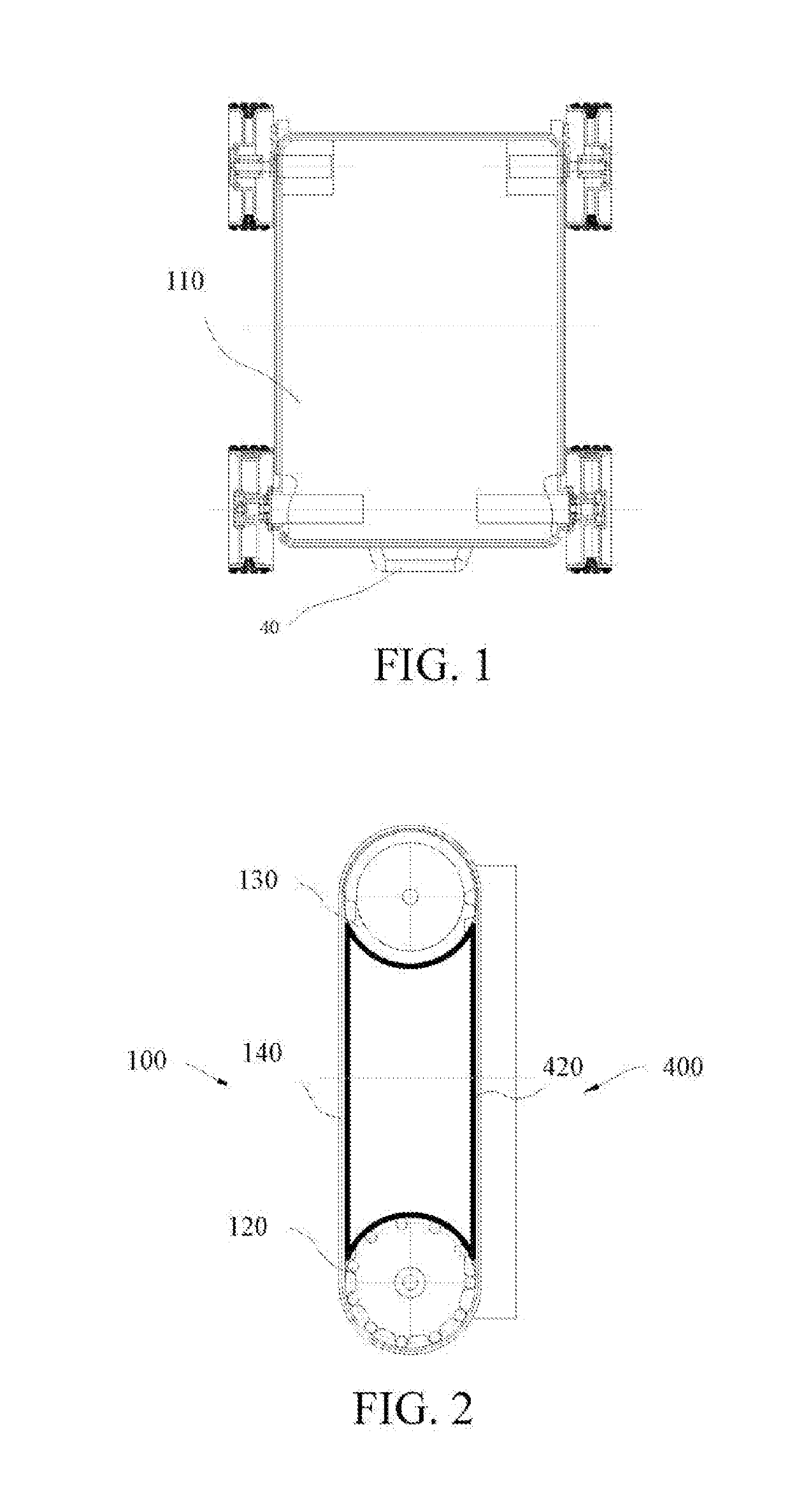
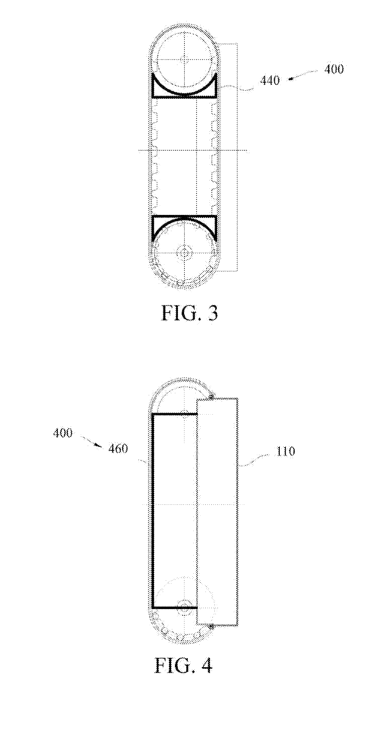
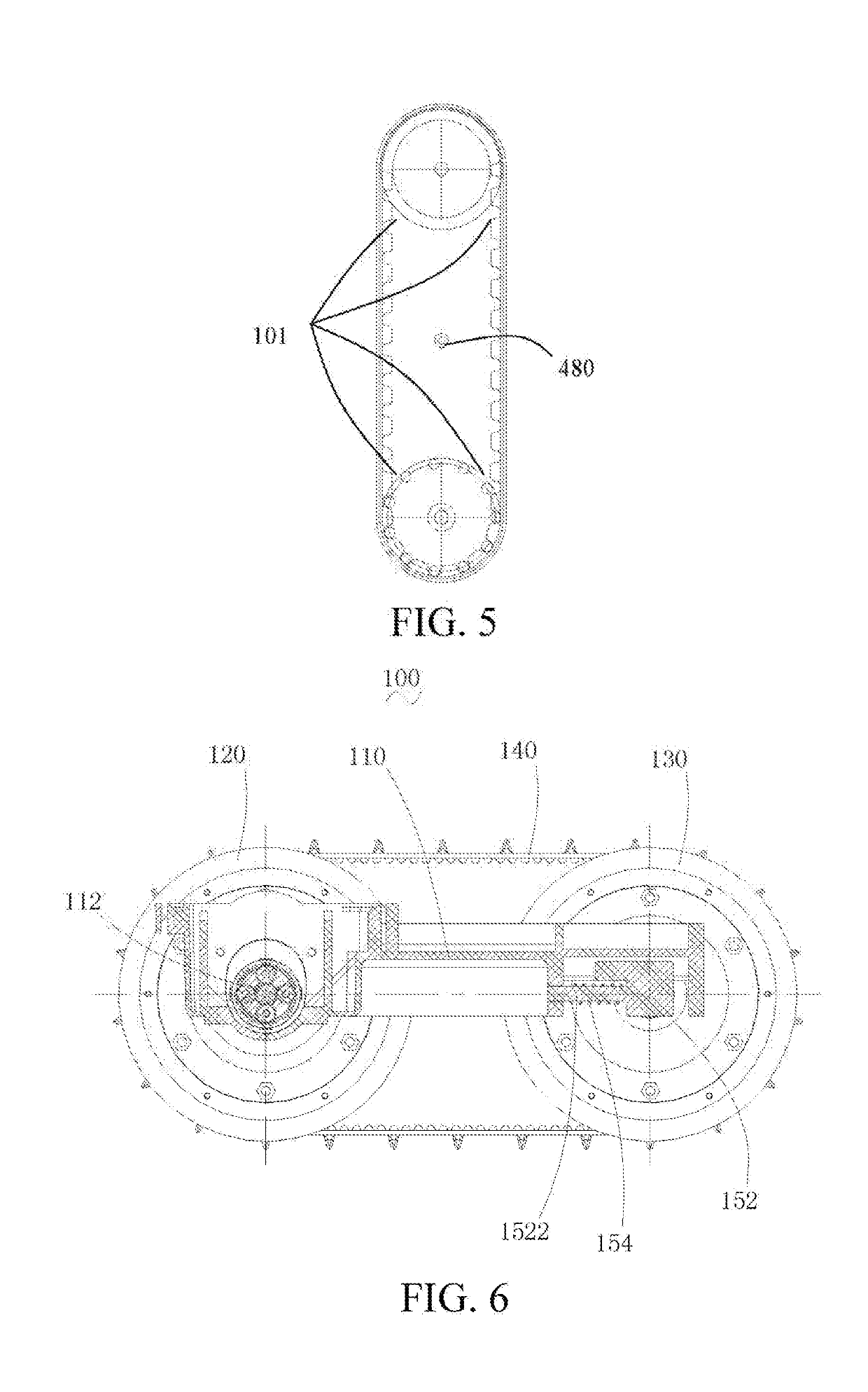
[0068]Referring to FIG. 6, Embodiment 1 provides a track mechanism 100 that can be applied to various tools requiring a track mechanism. In this embodiment, for example, the tool is a lawn mower. The track mechanism is suitable for operating environments with various working conditions, and especially has a significant advantage in a workplace having a ditch or a slope. Besides, for the lawn mower using the track mechanism as a walking mechanism, since the track has a relatively large covered area on the ground, a pressure against the lawn can be reduced, thereby reducing abrasion of the lawn.

[0069]Referring to FIG. 6, the track mechanism 100 includes a base 110, a driving wheel 120, a guide wheel 130, a track 140, and a tensioning mechanism. The tensioning mechanism is configured to adjust a position of the guide wheel 130, and change the position of the guide wheel 130 immediately when the track 140 becomes loose, so that the guide wheel 130 tensions the track 140 again and preven...

embodiment 2

[0085]Referring to FIG. 10 and FIG. 11, Embodiment 2 provides a track mechanism 1000 that can be applied to various tools requiring a track mechanism. Similarly, the track mechanism 200 can be applied to a lawn mower. The track mechanism 1000 includes a base 110, a driving wheel (omitted and not shown), a guide wheel 230, a track 240, and a tensioning mechanism.

[0086]Similarly, the track mechanism 200 can be applied to a lawn mower, and can be used as a chassis of the entire lawn mower. The driving wheel and the guide wheel 230 are used to support the base 210 together. The bottom of the driving wheel and the bottom of the guide wheel 230 are designed to be on a same horizontal plane. The radii of the driving wheel and the guide wheel 230 may be set to be consistent. The following mainly describes differences between Embodiment 1 and Embodiment 2.

[0087]Referring to FIG. 11, the tensioning mechanism includes an adjusting member 252 and an elastic member 254. The adjusting member 252 ...

embodiment 3

[0089]Referring to FIG. 12 and FIG. 13, Embodiment 3 provides a track mechanism 300 that can be applied to various tools requiring a track mechanism. The track mechanism 300 includes a base 310, a driving wheel (omitted and not shown), a guide wheel 330, a track 340, and a tensioning mechanism.

[0090]Similarly, the track mechanism 300 can be applied to a lawn mower and can be used as a chassis of the entire lawn mower. The driving wheel and the guide wheel 330 are used to support the base 310 together. The bottom of the driving wheel and the bottom of the guide wheel 330 are designed to be on a same horizontal plane. The radii of the driving wheel and the guide wheel 330 may be set to be consistent. The following mainly describes differences between Embodiment 3 and Embodiment 2.

[0091]Referring to FIG. 13, the tensioning mechanism includes an adjusting member 352 and an elastic member 354. The adjusting member 352 includes a first support shaft 3522 rotatably supported on the base 31...


PUM


Abstract

Embodiments of the present invention discloses a track mechanism, including a base; a driving wheel, disposed on the base rotatably; a guide wheel, configured to support the base together with the driving wheel and disposed movably relative to the base; a track, wound around the driving wheel and the guide wheel for a circle, to perform rotary motion around the driving wheel and the guide wheel; and a tensioning mechanism, including an adjusting member connected to the guide wheel to change a position of the guide wheel and an elastic member located between the adjusting member and the base, the elastic member provides a driving force that enables the adjusting member to move, and the adjusting member drives the guide wheel to move and tension the track.

Description

BACKGROUNDTechnical Field[0001]The present invention relates to the field of autonomous moving devices, and particularly, to an autonomous track-type moving device.Related Art[0002]As a mechanical tool for mowing vegetation, a lawn mower comprises a cutter head, a motor, a walking mechanism, and in some cases a hand rail. A blade is mounted on the cutter head, an output shaft of the motor is connected to the blade on the cutter head, and the blade is driven by the motor rotating at a high speed to mow a lawn, thereby achieving high working efficiency, saving working time of a lawn-mowing worker, and reducing a large amount of human resources. Compared with a common lawn mower, a track-type lawn mower can reduce a grounding pressure, protect vegetation, and resolve a problem that it is difficult to mow a lawn on a slope.SUMMARY[0003]Tracks, driving wheels, and guide wheels of a conventional track-type lawn mower are all visible, and when the track-type lawn mower is working, a user m...

Claims


Application Information

Patent Timeline
Patent Type & Authority Applications(United States)
IPC IPC(8): B62D55/065B62D55/24B62D55/30
CPCB62D55/065B62D55/242B62D55/244B62D55/30A01D34/835B62D55/10
Inventor RAN, YUANZHONGSONG, KANG
Owner POSITEC POWER TOOLS (SUZHOU) CO LTD
Why Eureka
Try Eureka