Scavenge pump

Active Publication Date: 2019-04-25
YAMADA SEISAKUSHO KK
View PDF5 Cites 0 Cited by
  • Summary
  • Abstract
  • Description
  • Claims
  • Application Information

AI Technical Summary

Benefits of technology

The present invention aims to improve lubrication between parts in a pump to prevent mixing of air and deliver oil quickly to parts that need it to operate smoothly. The invention achieves this by creating a groove that allows oil to be fed between parts during pump operation, which helps to achieve lubrication between parts. This results in a smoother rotation of the rotor and prevents air from entering the pump.

Problems solved by technology

Since hardly any oil remains inside, when the engine is re-started, the oil pump is not sufficiently capable of forming an oil film between the teeth of outer and inner rotors that form the rotor, or between an inner surface of a rotor chamber and side faces or an outer circumferential surface of the outer rotor, which would lead to problems such as progress of wear and increase of sliding resistance.
However, this publication does not show a structure that improves lubrication of a radial gap between a main body 1a and a main shaft 3.

Method used


Image

  • Scavenge pump
  • Scavenge pump
  • Scavenge pump

Examples


first embodiment

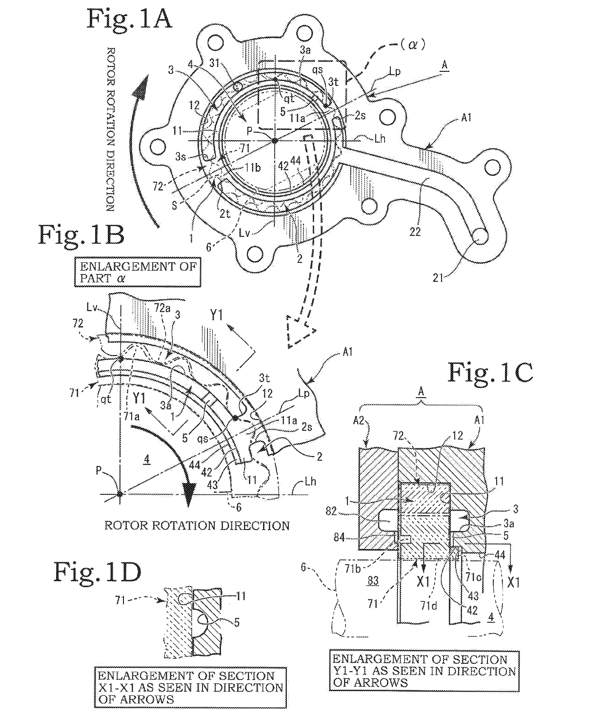
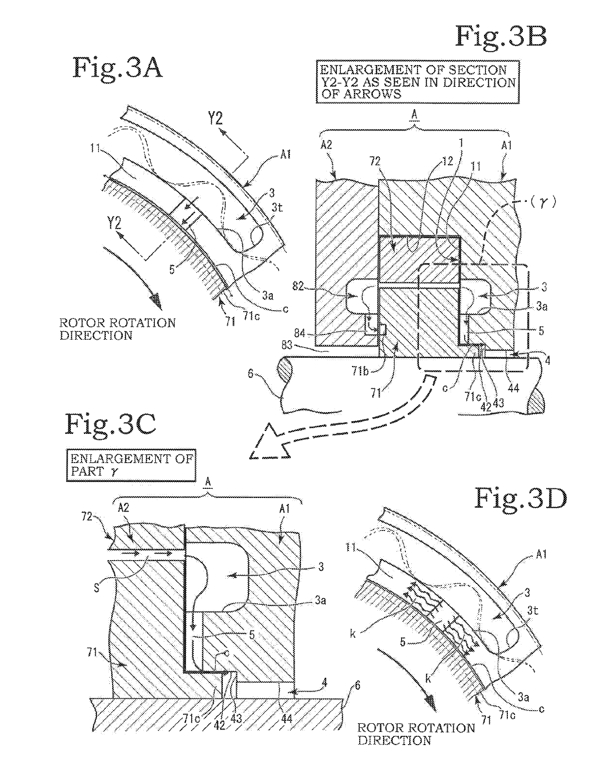
[0042]The groove 5 may be embodied in various forms. In the first embodiment, it is formed straight (see FIG. 1B, FIG. 3A and so on). In this embodiment, the trailing end 3t of the outlet port 3 and the bearing hole 4 can be connected with the shortest distance, so that the oil can be pumped out between the bearing hole 4 and the drive shaft 6 in the shortest time possible after the start-up of the scavenge pump.

second embodiment

[0043]There is a second embodiment wherein the groove 5 is formed in plurality (see FIG. 7). The amount of oil fed to the bearing hole 4 is thereby increased so that more oil can be supplied to the clearance c between the inner circumferential surface of the bearing hole 4 and the outer circumferential surface of the drive shaft 6, whereby the favorable lubricated condition of the drive shaft 6 can be maintained, and air mixing can be prevented.

[0044]The inner rotor 71 has a tooth profile, specifically, shapes such as trochoidal, ellipsoidal, higher-order curve, and so on. A plurality of outer teeth 71a, 71a . . . are formed on the inner rotor 71, while a plurality of inner teeth 72a, 72a . . . are formed on the outer rotor 72. As the inner rotor 71 rotates, with the outer teeth 71a and inner teeth 72a mated with each other, the outer rotor 72 is rotated. In the second seal land 11b, the outer teeth 71a and inner teeth 72a form a closed space, i.e., cell (interteeth space) S to carr...


PUM


Abstract

A scavenge pump includes: a pump housing including a housing body and a cover member, the housing body having a rotor chamber in which an inlet port, an outlet port, and a bearing hole formed by shaft holes with varying diameters with a stepped surface therebetween are provided; an outer rotor housed in the rotor chamber and having inner teeth; an inner rotor having outer teeth and a shaft support hole; and a drive shaft inserted or fixedly attached to the shaft support hole. The bearing hole includes a stepped inner circumferential part having a larger diameter than that of the drive shaft at an open peripheral edge on one side facing the rotor chamber, and a groove that extends through between a point close to a trailing end of the outlet port and the stepped inner circumferential part is formed.

Description

BACKGROUND OF THE INVENTION1. Field of the Invention[0001]The present invention relates to a scavenge pump, which is a type of gear oil pump capable of achieving a favorable lubricated condition in a short time immediately after start-up, and which is capable of delivering oil quickly after start-up to a rotor chamber, a rotor, a drive shaft, and so on.2. Description of the Related Art[0002]Internal gear oil pumps are well known as oil pumps. Oil pumps for vehicles, such as feed pumps that draw oil from an oil pan and feed the oil to various parts of an engine, and scavenge pumps that return the oil after being fed to various parts of the engine and used for lubrication and the like back to the oil pan, have long been used in many vehicles and widely known. A scavenge pump is not necessarily installed in every vehicle. When the engine has a structure whereby the oil fed to various parts of the engine returns to the oil pan on its own, the scavenge pump is often not required.[0003]Fo...

Claims


Application Information

Patent Timeline
IPC IPC(8): F04C15/00F01M1/02F04C2/10
CPCF04C15/0088F01M1/02F04C2/10F01M2001/0238F04C2/086F04C2/102F04C2240/60
Inventor KANEKO, ATSUSHIHOSOYA, KEI
Owner YAMADA SEISAKUSHO KK
Why Eureka
Try Eureka