Full-Color Led Diplay Panel And Method For Manufacturing Same

Inactive Publication Date: 2020-12-31
V TECH CO LTD
View PDF0 Cites 0 Cited by
  • Summary
  • Abstract
  • Description
  • Claims
  • Application Information

AI Technical Summary

Benefits of technology

The present invention provides a full-color LED display panel that can prevent mixing of colors between adjacent fluorescent layers. This is achieved by depositing a light shielding member on the peripheral face of the fluorescent layer, which prevents the collapse of a partition wall between adjacent layers and leakage of the fluorescent resist solution into an adjacent pixel for another color. Overall, the invention ensures reliable prevention of color mixing.

Problems solved by technology

Therefore, when loading a fluorescent resist solution containing a fluorescent colorant (pigment or dye) of the corresponding color into openings (pixels) for each color surrounded by the partition walls, a part of the partition wall may collapse, and the fluorescent resist solution may leak into an adjacent opening for another color.
Thus, there is a concern that this may result in colors being mixed.
In particular, these problems become particularly notable when the partition walls have great height-to-width aspect ratios.

Method used


Image

  • Full-Color Led Diplay Panel And Method For Manufacturing Same
  • Full-Color Led Diplay Panel And Method For Manufacturing Same
  • Full-Color Led Diplay Panel And Method For Manufacturing Same

Examples


first embodiment

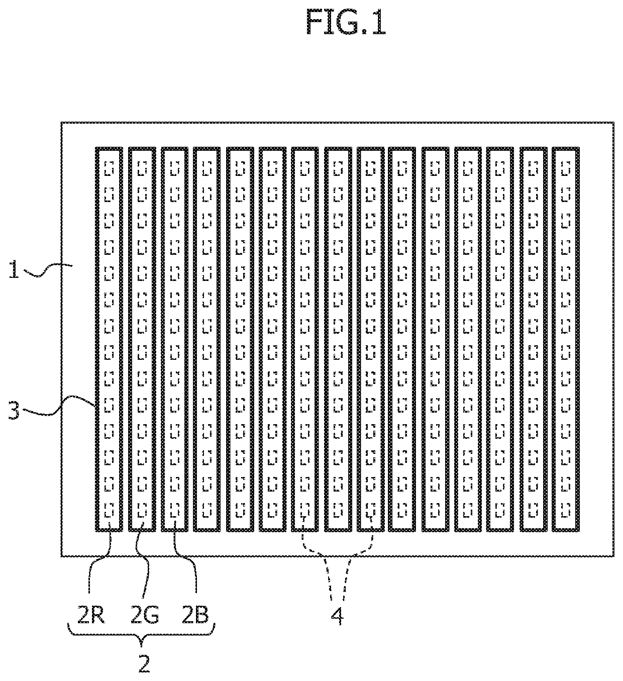
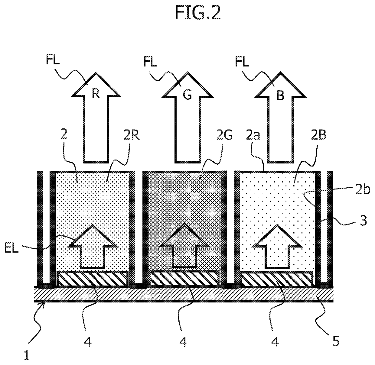
[0026]Hereinbelow, embodiments of the present invention will be described in detail with reference to the accompanying drawings. FIG. 1 is a plan view showing a full-color LED display panel according to the present invention. FIG. 2 is an enlarged cross-sectional view of the main part of FIG. 1. The full-color LED display panel displays images in full color, and includes an LED array substrate 1, fluorescent layers 2, and a light shielding member 3.

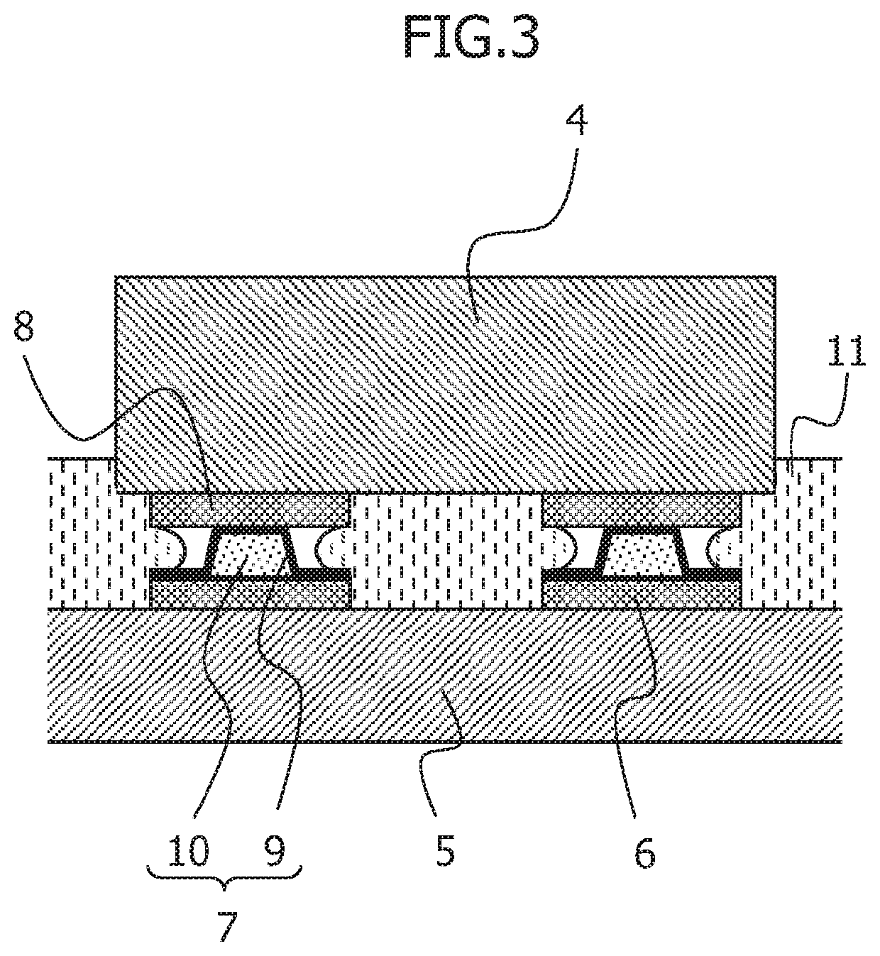
[0027]The LED array substrate 1 is provided with multiple LEDs 4 arranged in a matrix form, as shown in FIG. 1. The LED array substrate 1 includes the multiple LEDs 4 arranged on a wiring board 5, which includes a flexible board or a TFT drive board including wiring for supplying a drive signal to each LED 4 from a drive circuit provided externally, and for driving the LEDs 4 individually to be ON and OFF to turn the LEDs 4 on and off

[0028]The multiple LEDs 4 are provided on the wiring board 5, as shown in FIG. 2. Each LED 4 emits light i...

second embodiment

[0059]FIG. 9 is an enlarged cross-sectional view of the main part of a full-color LED display panel according to the present invention.

[0060]The second embodiment is different from the first embodiment in that the fluorescent layers 2 and the light shielding member 3 are formed on another transparent substrate 15, which is different from the LED array substrate 1. Hereinbelow, a manufacturing method according to the second embodiment will be described.

[0061]The manufacturing method according to the second embodiment can be roughly divided into a process for manufacturing an LED array substrate, a process for manufacturing a fluorescent layer array substrate, and an assembling process.

[0062]The process for manufacturing an LED array substrate is the same as that in the manufacturing method according to the first embodiment, and description thereof will be omitted.

[0063]FIGS. 10A to 10F are explanatory views showing the process for manufacturing a fluorescent layer array substrate.

[00...


PUM


Abstract

The present invention is a full-color LED display panel including: an LED array substrate 1 in which multiple LEDs 4 are arranged in a matrix form on a wiring board 5, each LED 4 emitting light in an ultraviolet or blue wavelength band; multiple fluorescent layers 2 configured to perform wavelength conversion by being excited by excitation light emitted from a corresponding LED 4 and by emitting fluorescence of a corresponding color, each fluorescent layer 2 being formed in an island pattern, on at least one corresponding LED 4 for red, green, or blue color, and being made of a fluorescent resist containing a fluorescent colorant uniformly dispersed in a photosensitive resin; and a light shielding member 3 that reflects or absorbs excitation light and fluorescence, and is deposited on a peripheral face 2b of each fluorescent layer 2, which is other than a light emitting surface 2a.

Description

[0001]This application is a continuation application of PCT / JP2019 / 001987, filed on Jan. 23, 2019.FIELD OF THE INVENTION[0002]The present invention relates to full-color LED display panels including fluorescent layers, and more specifically, relates to full-color LED display panels capable of reliably preventing mixing of colors occurring between adjacent fluorescent layers, and methods for manufacturing the full-color LED display panels.DESCRIPTION OF RELATED ART[0003]A conventional full-color LED display panel is provided with: an array of micro LED devices, each emitting blue (e.g., 450 nm to 495 nm) light or deep blue (e.g., 420 nm to 450 nm) light; and an array of wavelength conversion layers (fluorescent layers) disposed over the array of the micro LED devices, each wavelength conversion layer absorbing the blue or deep blue light emitted from a corresponding micro LED device to convert the emission wavelength into the wavelength of red, green, or blue light (see, for example,...

Claims


Application Information

Patent Timeline
IPC IPC(8): H01L27/15H01L33/50H01L33/60H01L33/00H01L33/48
CPCH01L33/486H01L33/005H01L33/504H01L2933/0066H01L33/60H01L27/156H01L2933/0041H01L33/50G09F9/33G09F9/30H01L25/0753H01L33/58H01L2933/0058H01L33/44
Inventor KAJIYAMA, KOICHIHIRANO, TAKAFUMI
Owner V TECH CO LTD
Why Eureka
Try Eureka