
Carriage for supporting and guiding a flap and airfoil flap system for use in an aircraft

a technology for supporting and guiding aircraft and airfoil flaps, which is applied in the direction of sliding contact bearings, mechanical equipment, transportation and packaging, etc., can solve problems such as complex construction, and achieve the effect of simple and load-optimized design, improving the cost-efficiency and reliability of airfoil flap systems

Inactive Publication Date: 2019-05-02
AIRBUS OPERATIONS GMBH
View PDF0 Cites 2 Cited by
  • Summary
  • Abstract
  • Description
  • Claims
  • Application Information

AI Technical Summary

Benefits of technology

The invention is about a carriage that supports and guides an aircraft flap. It has a simple design that reduces loads and makes it more efficient and reliable. The invention also includes an airfoil flap system for use in aircrafts that use this carriage.

Problems solved by technology

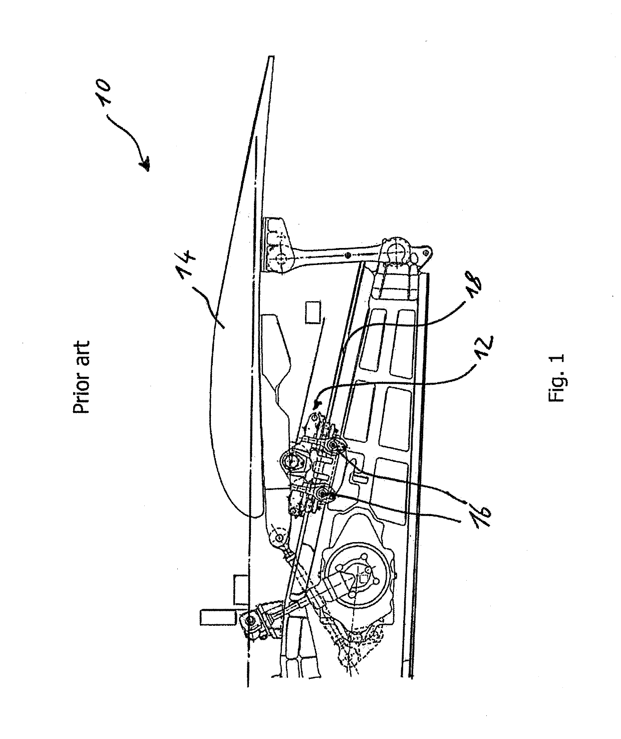
Such conventionally known flap arrangements have a complex construction requiring a complex support and drive mechanism for selectively extending and retracting the flap arrangement.

Method used


Image

  • Carriage for supporting and guiding a flap and airfoil flap system for use in an aircraft
  • Carriage for supporting and guiding a flap and airfoil flap system for use in an aircraft
  • Carriage for supporting and guiding a flap and airfoil flap system for use in an aircraft

Examples


first embodiment

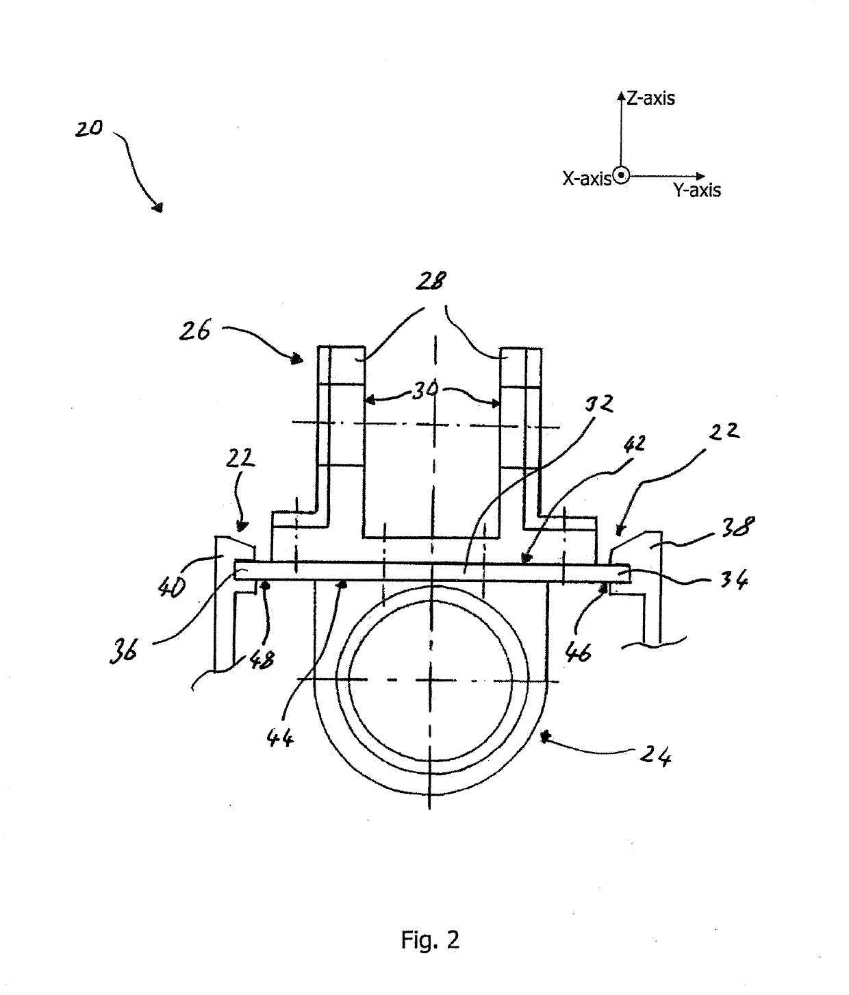
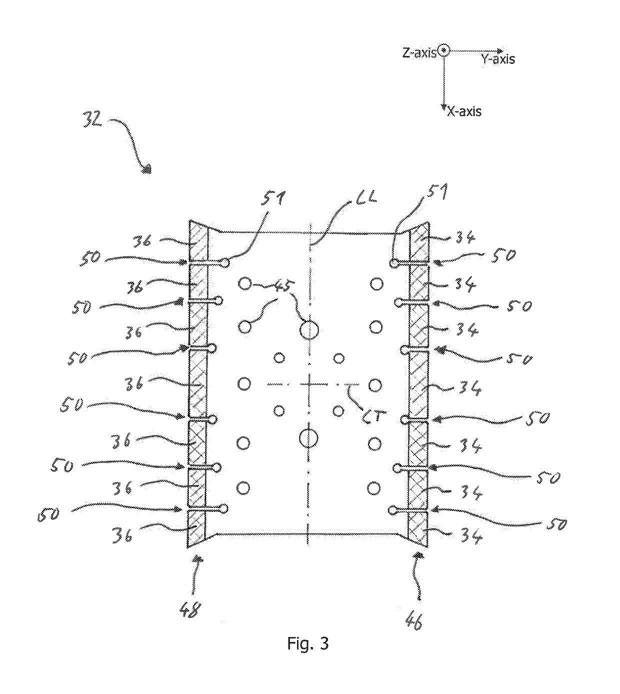
[0028]FIGS. 2 and 3 show a carriage 20 for supporting and guiding an aircraft flap according to a The flap supported and guided by the carriage 20 forms a part of an airfoil, such as a wing of the aircraft, and is connected to a main body of the airfoil. The carriage 20 is translationally moveable along a linear slide bearing 22. The linear slide bearing 22 is designed to provide free motion of the carriage 20 along one axis. Specifically, in the shown embodiment, a free motion of the carriage 20 along an X-axis normal to an image plane of FIG. 2 is provided. Further, the carriage 20 is configured to, upon being translationally moved along the linear slide bearing 22, actuate the flap so as to move the flap between an extended and retracted position. For actuating the flap, the carriage 20 comprises a drive element 24 connectable to an actuator for receiving a translational actuating force causing a translation of the carriage 20 along the slide bearing 22 in a direction along the ...

second embodiment

[0036]FIGS. 4 to 7 show a carriage 20 for supporting and guiding the aircraft flap according to a Compared to the carriage 20 shown in FIGS. 2 and 3, the first and the second slide elements 34, 36 are partially provided in form of attachments 52 detachably connected to the opposing edge regions 46, 48 of the slide plate 32.

[0037]FIG. 4 shows the carriage 20 which is engaged to the slide rails 38, 40 of the linear slide bearing 22 via the first and the second slide elements 34, 36 in two states. First, as can be gathered from the left side of FIG. 4, the carriage 20 is shown in a loaded state, i.e., during a flight operation of the aircraft. To that end, as can be gathered from the right side of FIG. 4, the carriage 20 is shown in an unloaded state, i.e., during a ground operation of the aircraft. In the loaded state, the attachments 52 are in contact with the slide rails 38, 40 with both a lateral surface 54 and an upper surface 56 of the attachments 52. In the unloaded state, the ...


PUM


Abstract

A carriage for supporting and guiding an aircraft flap translationally moveable along a linear slide bearing comprises a drive element connectable to an actuator for receiving a translational actuating force causing a translation of the carriage along the slide bearing. A flap support of the carriage is configured to, upon translational movement of the carriage, transmit the actuating force to the flap. The carriage further has a slide plate with at least two slide elements arranged on opposed sides of the slide plate which are engageable to at least two corresponding linear slide rails of the slide bearing.

Description

CROSS-REFERENCES TO RELATED APPLICATIONS[0001]This application claims the benefit of the German patent application No. 10 2017 125 381.5 filed on Oct. 30, 2017, the entire disclosures of which are incorporated herein by way of reference.BACKGROUND OF THE INVENTION[0002]The present invention refers to a carriage for supporting and guiding an aircraft flap and to an aircraft flap system equipped with a carriage of such type.[0003]Aircraft airfoils are designed such that their geometry of the airfoil profile is adjustable or adaptable to the varying boundary conditions prevailing in different states of the course of a flight, such as during landing, take-off or cruise. Flap arrangements are known for selectively actuating a flap connected to an airfoil main body to extend into or retract from an air flow boundary layer of the airfoil so as to selectively vary the aerodynamic lift generated by the airfoil. Such conventionally known flap arrangements have a complex construction requiring...

Claims


Application Information

Patent Timeline
IPC IPC(8): B64C13/28B64C9/02B64C9/14F16C17/02F16C33/20
CPCB64C13/28B64C9/02B64C9/14F16C17/02F16C33/201B64C3/50B64C9/18Y02T50/10Y02T50/30
Inventor GARTELMANN, RAINER
Owner AIRBUS OPERATIONS GMBH
Learn More