Grid Plate for Laying Tile on Uneven Surfaces

a grid plate and tile technology, applied in the field of grid plates for laying tiles, can solve the problems of inability to disclose a grid plate for laying mosaic tiles, excessive or lack of thinset, etc., and achieve the effect of facilitating the distribution of thinset and facilitating flush and level laying of tiles

a grid plate and tile technology, applied in the field of grid plates for laying tiles, can solve the problems of inability to disclose a grid plate for laying mosaic tiles, excessive or lack of thinset, etc., and achieve the effect of facilitating the distribution of thinset and facilitating flush and level laying of tiles

US20190127991A1Inactive Publication Date: 2019-05-02SANTANA LUIS

Image

  • Grid Plate for Laying Tile on Uneven Surfaces
  • Grid Plate for Laying Tile on Uneven Surfaces
  • Grid Plate for Laying Tile on Uneven Surfaces

Examples


Embodiment Construction

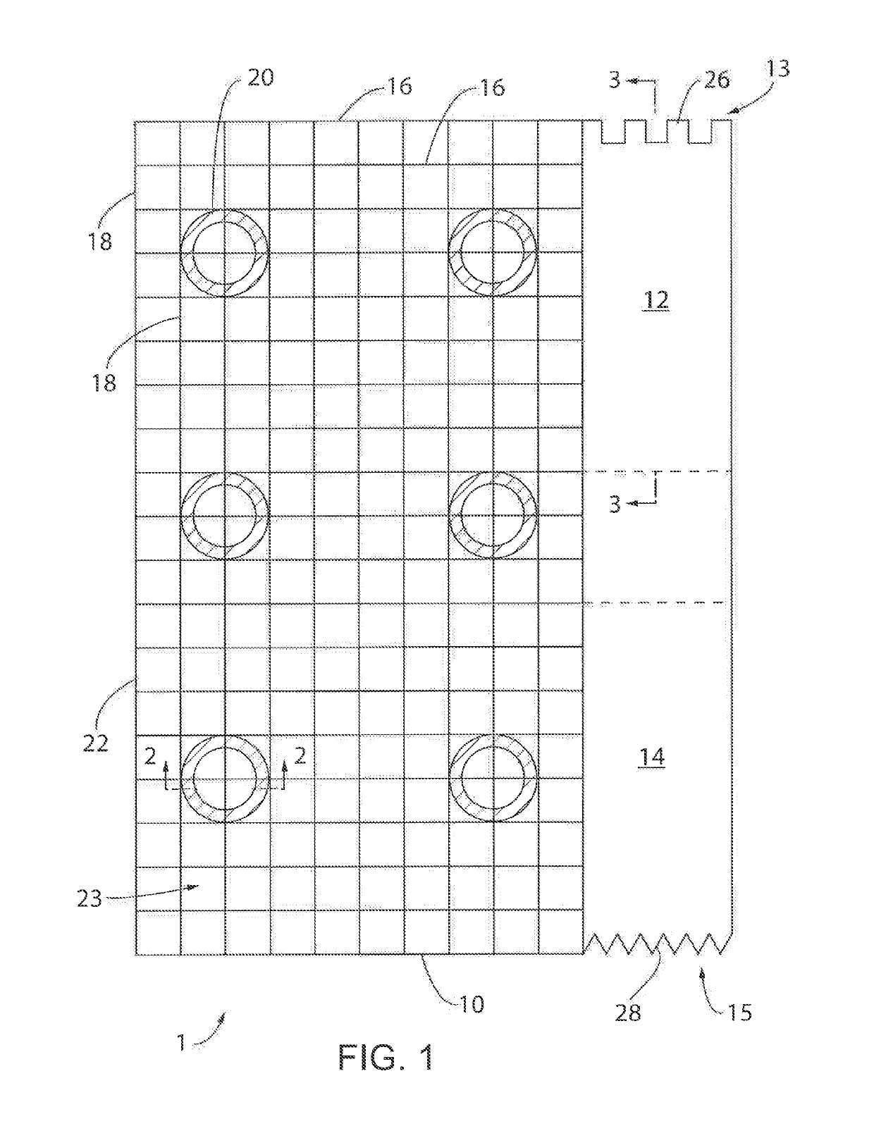
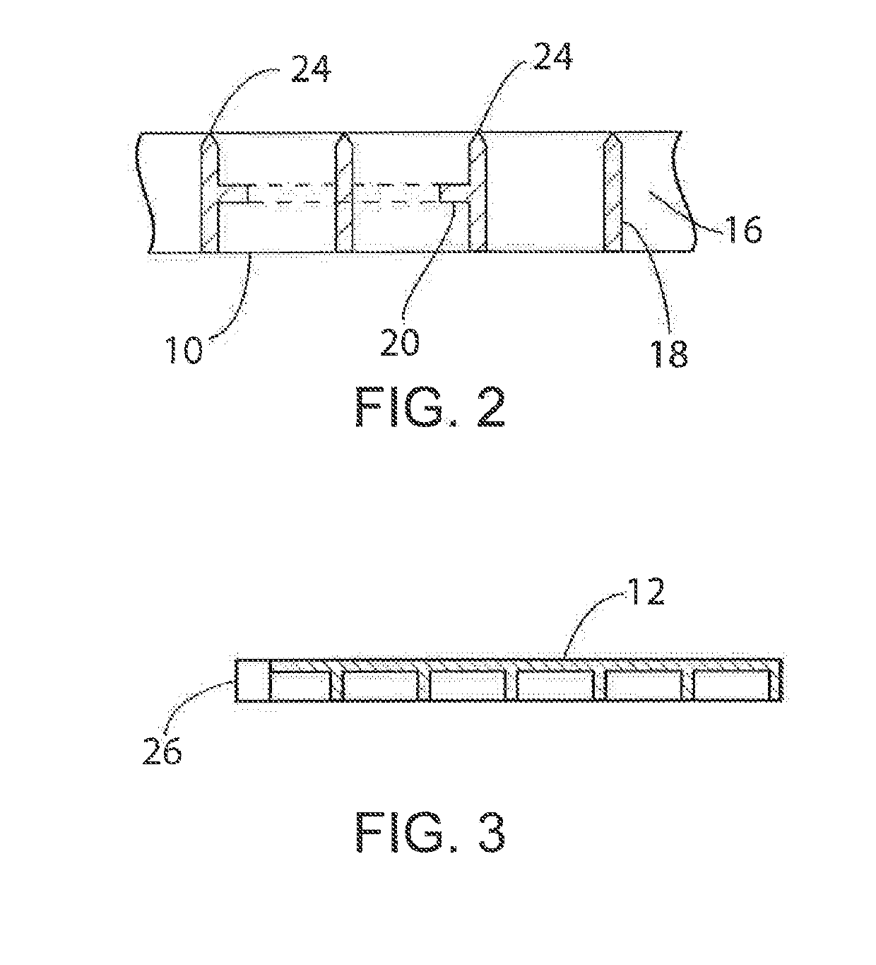
[0043]With reference now to the drawings, and particularly to FIG. 1, there is shown a top view of a grid plate assembly 1. The grid plate assembly 1 preferably includes a grid plate member 10, a detachable large groove tile trowel 12, and a detachable small groove tile trowel 14. It is understood that the grid plate 1 may be sold as a kit allowing the user to complete the leveling tile task with the assistance of detachable tools also included in the kit.

[0044]While the grid plate assembly 1 includes multiple attached and detachable elements, it is understood that the grid plate assembly 1 may only include the grid plate member 10 without the detachable tile trowels 12, 14 or other attachments. In alternative embodiments, the grid plate assembly 1 may include other or additional tiling tools, such as multi-sized tile trowels and depth measurement tools, as further described below.

[0045]In one embodiment the grid plate member 10 may be a rectangular sheet of material, in one embodim...


PUM

PropertyMeasurementUnit
sizeaaaaaaaaaa
thicknessaaaaaaaaaa
heightaaaaaaaaaa

Abstract

A grid plate for laying mosaic tile preferably includes a grid plate member and detachable tile trowels and / or depth tools. The grid plate member includes a plurality of transverse strips, a plurality of lengthwise strips, and a plurality of retention elements. The plurality of transverse and lengthwise cross strips form a grid pattern. It is preferable that a top of the plurality of transverse and lengthwise strips be brought to an edge to facilitate the distribution of thinset. The plurality of retention elements are integrally molded into the grid pattern to secure the grid plate to a tile cavity.

Description

CROSS-REFERENCE TO RELATED APPLICATIONS[0001]This application claims the benefit of U.S. Provisional Application No. 62 / 579,924, filed Nov. 1, 2017, and hereby incorporated by reference.BACKGROUND OF THE INVENTION[0002]The present invention relates generally to laying tile, and more specifically, to a grid plate for laying tile, which facilitates the flush and level laying of the tile in a cavity.[0003]Mosaic tiles, mosaic medallions, decorative tiles and the like are used as accents between lesser attractive tiles and other flooring objects. However, a height of the adjacent tile or objects is usually greater, which results in excessive or a lack of thinset being applied. More experienced tiling professionals may be able to lay the mosaic tiles flush and level with the existing tiles. However, it will be more work for a less experienced tiling professional to lay the mosaic tiles flush and level. The prior art does not disclose a grid plate for laying mosaic tile.[0004]Accordingly,...

Claims


Application Information

Patent Timeline
02 May 2019
Publication
US20190127991A1
IPC
E04F15/02; E04C2/42; E04B5/02
CPC
E04F15/02194; E04C2/42; E04C2/50; E04C2/427; E04F15/0215; E04F15/18
Inventors
SANTANA, LUIS