Laser Pipe Positioning System

Active Publication Date: 2019-05-02
SANTUCCI NICHOLAS
View PDF0 Cites 0 Cited by
  • Summary
  • Abstract
  • Description
  • Claims
  • Application Information

AI Technical Summary

Benefits of technology

The present invention provides an improved laser-guided positioning system for positioning pipes. The system minimizes positioning errors, utilizes GPS tracking of a marker, and reduces errors caused by improper sighting by users. Additionally, the system is easy to set up and utilize, self-corrects when misaligned, and can be utilized within a trench.

Problems solved by technology

Laying pipe for different applications, such as for sewers, rainwater run-off, or other like applications, is often difficult.
However, the excavation and direction of the ongoing trench, and the pipe that is subsequently positioned within the trench must be carefully planned otherwise pipes may not align.
This system was often time-consuming to construct and difficult to work with.
Specifically, it was often difficult to dig a trench and position pipe with the complicated batten structure above ground.
Moreover, because the sighting cord or string was above ground, and the plumb bob was used to align the sighting cord or string with the pipe, variances in any portion of the system were often disastrous.
However, errors can be caused by improper alignment or sighting of the stake by the person above ground and improper usage of the plumb bob for positioning of the laser beam.
Since the stake is typically a relatively long distance from the start of the pipe run, any error in sighting can cause a serious misalignment of the laser beam within the trench.
For example, in the process of digging the subsequent trench and positioning the subsequent pipe, machinery may cause earth to compact, or may cause vibrations that may misalign the laser beam.
If not detected, differences in laser beam position can cause subsequent pipe to be incorrectly positioned.

Method used


Image

  • Laser Pipe Positioning System
  • Laser Pipe Positioning System

Examples


Embodiment Construction

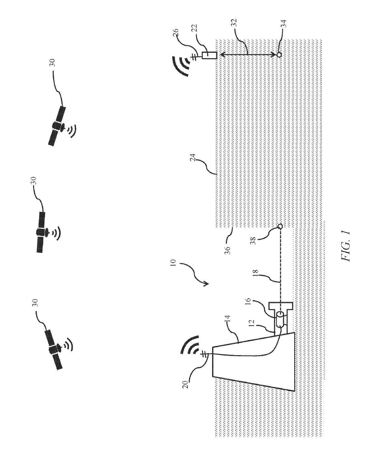
[0042]The present invention relates to a GPS-guided laser pipe positioning system and methods of using the same. More specifically, a target marker is placed a distance from a laser beam source and the target marker has a GPS tracker thereon, wherein the laser beam source tracks the precise location of the target marker through the GPS tracker. The laser beam is then aimed at the location of the GPS tracker, or at a location an offset distance, such as displaced vertically downward under the ground such that the laser beam is aimed at the location within a trench for positioning pipe therein.

[0043]As illustrated in FIG. 1, a GPS-guided laser pipe positioning system is shown and described in an embodiment of the present invention. Specifically, a trench 10 is shown having a segment of pipe 12 that may be connected to a structure 14, such as a riser, or sewer access or other like access as apparent to one of ordinary skill in the art. Typically, a structure may provide a convenient lo...


PUM


Abstract

The present invention relates to a GPS-guided laser pipe positioning system and methods of using the same. More specifically, a target marker is placed a distance from a laser beam source and the target marker has a GPS tracker thereon, wherein the laser beam source tracks the precise location of the target marker through the GPS tracker. The laser beam is then aimed at the location of the GPS tracker, or at a location an offset distance, such as displaced vertically downward under the ground such that the laser beam is aimed at the location within a trench for positioning pipe therein.

Description

[0001]The present invention claims priority to U.S. Provisional Pat. App. No. 62 / 577,211, titled “GPS-Guided Laser Pipe Positioning System,” filed Oct. 26, 2017, which is incorporated herein by reference in its entirety.TECHNICAL FIELD[0002]The present invention relates to a laser pipe positioning system and methods of using the same. More specifically, a target marker is placed a distance from a laser beam source and the target marker has a GPS tracker thereon, wherein the laser beam source tracks the precise location of the target marker through the GPS tracker. The laser beam is then aimed at the location of the GPS tracker, or at a location an offset distance, such as displaced vertically downward under the ground such that the laser beam is aimed at the location within a trench for positioning pipe therein.BACKGROUND[0003]Laying pipe for different applications, such as for sewers, rainwater run-off, or other like applications, is often difficult. First, excavations are generall...

Claims


Application Information

Patent Timeline
IPC IPC(8): F16L1/10F16L1/028
CPCF16L1/10F16L1/028G01S19/14E02F5/145E03F3/06F16L1/06
Inventor SANTUCCI, NICHOLAS
Owner SANTUCCI NICHOLAS
Why Eureka
Try Eureka