Narrow frame display panel and display device

a display panel and narrow frame technology, applied in the field of display, can solve the problems of many problems in the cof scheme, the optical quality of the backlight module, etc., and achieve the effect of ensuring optical quality, reducing the width of the frame, and increasing the screen-to-body ratio

Inactive Publication Date: 2019-05-02
WUHAN CHINA STAR OPTOELECTRONICS TECH CO LTD
View PDF2 Cites 12 Cited by
  • Summary
  • Abstract
  • Description
  • Claims
  • Application Information

AI Technical Summary

Benefits of technology

[0016]In the disclosure, one end of a flexible circuit board is bound to a surface of the bonding end facing the color film substrate, the other end of the flexible circuit board is bound with a driving chip and arranged opposite to the color film substrate after being bent away from the light-exiting surface. Thus the flexible circuit board may not be seen outside the display panel. Therefore, the width of the frame may be reduced and the screen-to-body ratio may be increased. Meanwhile, the driving chip is located on a side of the flexible circuit board facing away from the color film substrate, and therefore may be away from the heated reflection sheet of the backlight module, and this ensures an optical quality without increasing the thickness of the display device. In addition, the black shielding layer on the outer surface of the array substrate may prevent the ambient light from illuminating metal electrodes on the inner surface of the array substrate to prevent specular reflection.

Problems solved by technology

However; the COF scheme also has many problems.
However, if the chip is a heat source and close to the reflector, it may easily cause an optical quality of the backlight module.

Method used


Image

  • Narrow frame display panel and display device

Examples


Embodiment Construction

[0019]In order to make the objectives, technical schemes and advantages of the disclosure more comprehensible, the disclosure is further described in detail below with reference to the accompanying drawings and embodiments. It should be understood that the specific embodiments described herein are merely used to explain the disclosure, and are not intended to limit the disclosure.

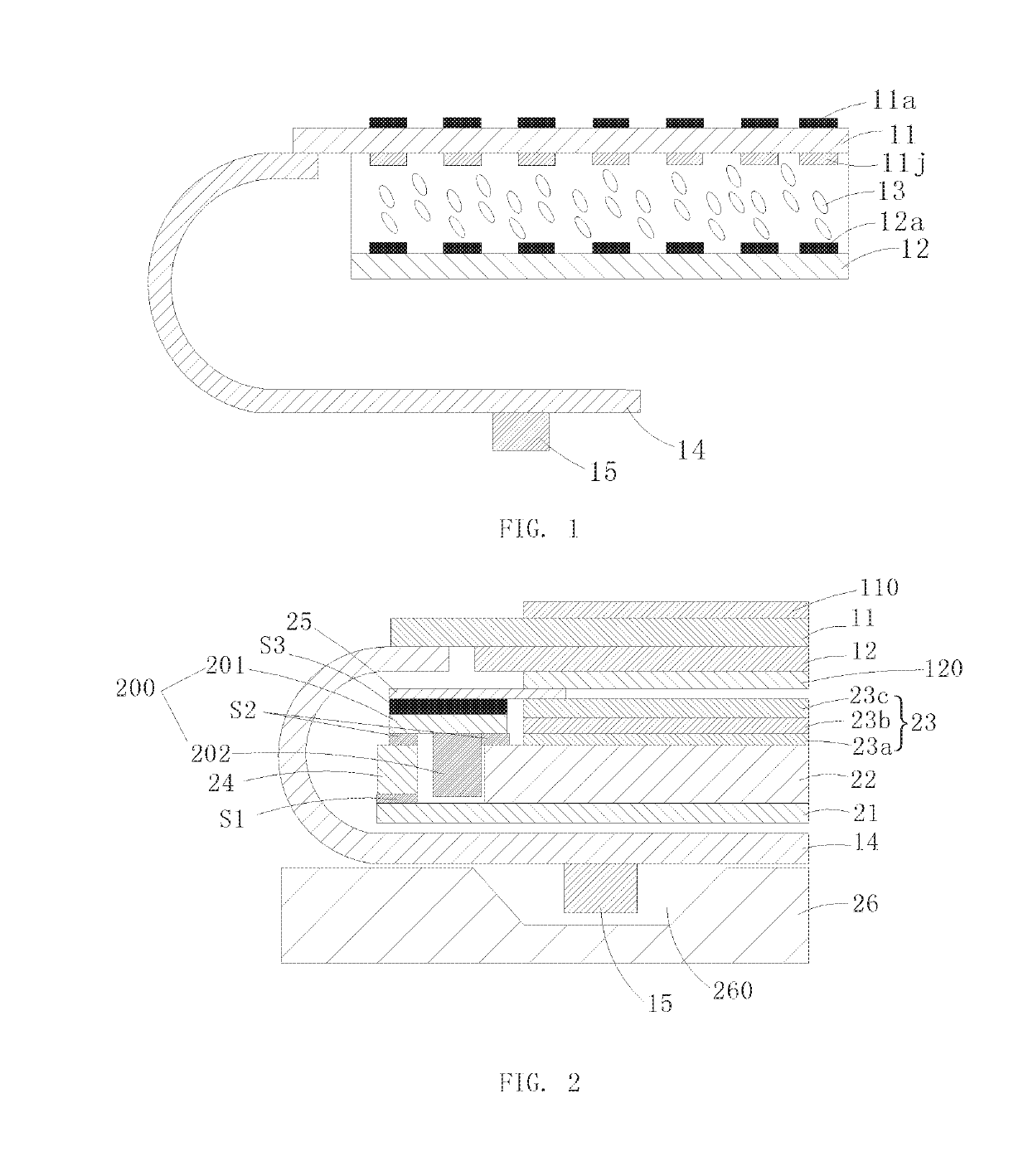
[0020]Refer to FIGS. 1 and 2, a narrow frame display panel according to an embodiment of the disclosure mainly includes an array substrate 11 and a color film substrate 12 arranged opposite to each other, a liquid crystal 13 filled between the array substrate 11 and the color film substrate 12, a flexible circuit board 14 and a driving chip 15. Different from the conventional display panel, a side located by the array substrate 11 in this embodiment is a light-exiting surface and a backlight source enters light from the side the color film substrate 12 located. The upper polarizer 110 and the lower polarize...


PUM

PropertyMeasurementUnit
flexibleaaaaaaaaaa
widthaaaaaaaaaa
heightaaaaaaaaaa

Abstract

The disclosure discloses a narrow frame display panel, comprising an array substrate, a color film substrate, a liquid crystal filled between the array substrate and the color film substrate, a flexible circuit board and a driving chip, wherein a side located by the array substrate is a light-exiting surface, and one end of the array substrate is a bonding end; one end of the flexible circuit board is bound to a surface of the bonding end facing the color film substrate, and the other end of the flexible circuit board is bound with a driving chip and arranged opposite to the color film substrate after being bent away from the light-exiting surface, and the driving chip is located on the side of the flexible circuit board facing away from the color film substrate. The disclosure further discloses a display device.

Description

RELATED APPLICATIONS[0001]The present application is a National Phase of International Application Number PCT / CN2017 / 110772, filed Nov. 14, 2017, and claims the priority of China Application No. 201711043755.X, filed Oct. 31, 2017.BACKGROUND OF THE INVENTION1. Field of the Invention[0002]The disclosure relates to a display technical field, and more particularly to a narrow frame display panel and a display device.2. The Related Arts[0003]At present, the popularity of full-screen mobile phones is getting higher and higher, and the screen with high screen proportion is getting more and more popular. As a result, a lot of narrow frame solutions are created, and the narrow frame solutions mainly aim at the left and right frames, but regarding to the mobile phones, raising the proportion of screen-to-body ratio to the lower frame is a big topic. The so-called screen-to-body ratio is the ratio of the screen area to the mobile phones area. A higher proportion of the screen-to-body ratio ma...

Claims


Application Information

Patent Timeline
Patent Type & Authority Applications(United States)
IPC IPC(8): G02F1/1333G02F1/1362G02F1/1335H05K1/18
CPCG02F2001/133317G02F2001/13332H05K2201/056G02B6/0055G02F1/133308G02B6/009G02F1/133512G02F1/133514H05K1/189H05K2201/10136G02F1/136209H05K1/147G02F1/13452G02B6/0086G02F1/133322G02F1/133314G02F1/13332G02F1/133317
Inventor CUI, HONGQINGLI, DEJIUNLUNG, PO-HUASONG, WENQING
Owner WUHAN CHINA STAR OPTOELECTRONICS TECH CO LTD
Why Eureka
Try Eureka