Back cover for electronic device and electronic device

a technology of electronic devices and back covers, which is applied in the direction of portable computer details, instruments, resonant antennas, etc., can solve the problems of affecting the signal quality of the antenna, reducing the frame space of the display panel, and achieving the design of narrow frame for notebook computers. , to achieve the effect of reducing the width of the frame, reducing the thickness of the electronic device, and achieving high-quality appearan

Active Publication Date: 2020-04-02
ACER INC
View PDF0 Cites 0 Cited by
  • Summary
  • Abstract
  • Description
  • Claims
  • Application Information

AI Technical Summary

Benefits of technology

[0016]Based on the above, the structural design of the first radiator, the second radiator and the ground radiator of the back cover of the disclosure allows the metal body to be directly used as an antenna structure, so that a substrate carrying the antenna structure may be omitted, and thus a thickness of the electronic device may be reduced. In addition, since it is not required for the antenna structure to be placed at a frame of the electronic device, a width of the frame may be reduced, thereby achieving the effect of narrow frame. In addition, since the back cover is made of metal, a high-quality appearance may be achieved.

Problems solved by technology

In order to prevent performance of antenna from being affected by the shielding effect of the metal material, current practice in the market is to set the antenna of the notebook computer inside the system, but with this configuration, the antenna is easily interfered by internal noise of the system and signal quality of the antenna is directly affected.
Another method is to support the antenna with a circuit board and move the antenna to a top side of a panel (the frame), which however makes it difficult for the frame space of a display panel to be reduced, and makes it difficult to achieve the design of narrow frame for the notebook computer.
Therefore, it is an urgent issue to find out how to adjust the antenna structure and design the notebook computer with both a metal body and a narrow frame.

Method used


Image

  • Back cover for electronic device and electronic device
  • Back cover for electronic device and electronic device
  • Back cover for electronic device and electronic device

Examples


Embodiment Construction

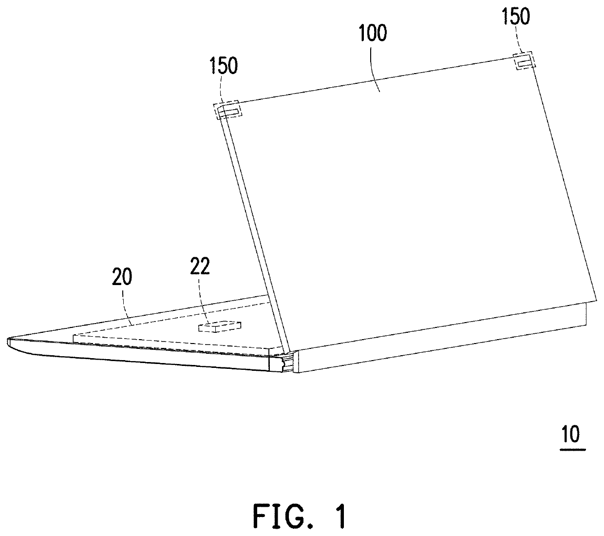
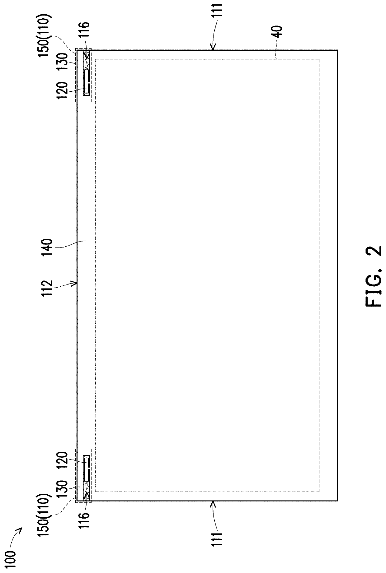
[0024]FIG. 1 is a schematic perspective view of an electronic device according to an embodiment of the disclosure. Referring to FIG. 1, an electronic device 10 of the exemplary embodiment is exemplified as a notebook computer, but the disclosure is not limited thereto. In other embodiments, the electronic device 10 may be other electronic devices such as a mobile phone or a tablet computer. In the exemplary embodiment, the electronic device 10 has an upper body and a lower body. The upper body includes a back cover 100, and the lower body includes a circuit board 20.

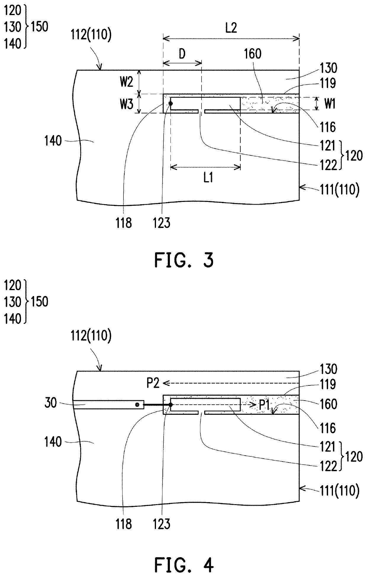
[0025]In the exemplary embodiment, the back cover 100 is provided with two antenna structures 150, wherein the two antenna structures 150 are in a symmetrical configuration and adjacent to a corner of the upper body of the electronic device 10. The circuit board 20 includes a wireless communication module 22. Two coaxial transmitting wires 30 (shown in FIG. 4) are extended from the upper body to the lower body to connect...


PUM


Abstract

A back cover includes a metal body having a first side, a second side, and a groove that is formed at the first side. The metal body further has a first radiator, a second radiator, and a ground radiator. The first radiator is disposed in the groove, and has a main portion and a support portion that cooperatively form a T-shape. The main portion includes a feeding end adjacent to a closed end of the groove. The second radiator is adjacently connected to the groove and is defined by the first and second sides, and an edge of the groove. The ground radiator is formed by a portion of the metal body excluding the first and second radiators. The second radiator and the support portion are connected to the ground radiator. The first and second radiators, and the ground radiator are serve as an antenna structure.

Description

CROSS-REFERENCE TO RELATED APPLICATION[0001]This application claims the priority benefit of Taiwan application serial no. 107134186, filed on Sep. 27, 2018. The entirety of the above-mentioned patent application is hereby incorporated by reference herein and made a part of this specification.BACKGROUND OF THE DISCLOSUREField of the Disclosure[0002]The disclosure relates to a back cover and an electronic device, and more particularly to a back cover which can constitute an antenna structure and an electronic device using such back cover.Description of Related Art[0003]In recent years, body of notebook computer is mostly made of metal, and appearance thereof is typically designed with a narrow frame to achieve a more beautiful look. In order to prevent performance of antenna from being affected by the shielding effect of the metal material, current practice in the market is to set the antenna of the notebook computer inside the system, but with this configuration, the antenna is easil...

Claims


Application Information

Patent Timeline
Patent Type & Authority Applications(United States)
IPC IPC(8): H01Q1/22G06F1/16H01Q1/24
CPCH01Q1/2266H01Q1/24G06F1/1698H01Q5/30G06F1/1616H01Q5/364H01Q9/42
Inventor HUANG, SHIH-TINGLIN, CHING-CHICHEN, CHIEN-WENWANG, CHUAN-CHUN
Owner ACER INC
Why Eureka
Try Eureka