Bone screw system

a screw system and bone technology, applied in the field of bone screw systems, can solve the problems of missing backward compatibility with existing implants, plate or nail modification, and the respective technical complexity of the mentioned concepts, so as to reduce the clearance, reduce the cost, and reduce the technical complexity

Active Publication Date: 2019-05-09
STRYKER EURO OPERATIONS HLDG LLC
View PDF5 Cites 0 Cited by
  • Summary
  • Abstract
  • Description
  • Claims
  • Application Information

AI Technical Summary

Benefits of technology

[0011]The bone screw system according to the invention may provide reduced technical complexity and reduced costs compared to prior art systems. The reason may be that no modifications of the washer bore are necessary. For example, no threads in the washer bore are necessary. Also a backward compatibility to existing implants, plates, nails or the like is provided. Further, conventional mass produced screws may be used.
[0012]Due to the slightly angled insertion of the screw, the bone screw system according to the invention may further provide a significantly decreased clearance and an increased, in particular axial stiffness and stability compared to prior art systems. The increased stiffness provided by the bone screw system according to the invention may lead to an in particular angular stable locking of implants, plates, nails or the like. The improved angular stable locking of implants may be associated with a positive impact on fracture healing. This is true especially for inherently unstable fracture situations in combination but not limited to short shaft fragments, wide intramedullary canals, poor bone qualities, and / or “distal” (opposite end to the targeting device adaptation) locking configurations like in the treatment of distal tibia fractures.

Problems solved by technology

However, the mentioned concepts suffer from their respective technical complexity, the required costly implant, plate or nail modification by e.g. additional threads, and a missing backward compatibility to existing implants, plates, nails or the like.

Method used


Image

  • Bone screw system
  • Bone screw system

Examples


Embodiment Construction

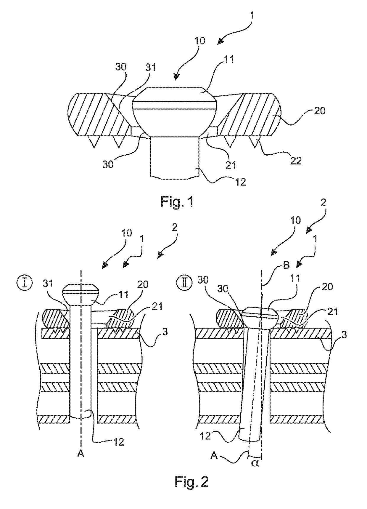
[0036]FIGS. 1 and 2 show schematically and exemplarily an embodiment of a bone screw system 1 according to the invention FIG. 2 shows schematically and exemplarily an embodiment of an implant system 2 according to the invention. The implant system 2 comprises the bone screw system 1 and an implant 3. The implant 3 is fixed to a bone by means of the bone screw system 1. The implant may be (part of) a plate, a nail, an intramedullary nail, a rod, a pin and the like. The bone screw system 1 can however also be used to be directly screwed into the bone without the implant.

[0037]The bone screw system 1 can be used for angularly locking a bone screw 10 into a bore. The bore is here provided in an implant. The implant bore is here a circular hole. The bone screw system 1 comprises a bone screw 10 and a washer 20. The screw 10 is here a standard bone screw. The screw 10 comprises a screw head 11 and a screw shaft 12. The washer 20 comprises a washer bore 21 without an internal thread.

[0038]...


PUM


Abstract

The invention relates to a bone screw system, an implant system and a method of locking a bone screw system into a bore. The bone screw system comprises a bone screw and a washer. The screw comprises a screw head and a screw shaft. The washer comprises a washer bore. A diameter of the washer bore is larger than an outer diameter of the screw shaft. This allows a displacement of the screw shaft within the washer bore. The diameter of the washer bore is smaller than an outer diameter of the screw head. This prevents the screw head from moving through the washer bore. The screw and the washer comprise each an engagement portion for an engagement with each other. At least one of these engagement portions comprises an inclined surface. The inclined surface is configured to force the screw shaft sideward upon screwing in of the screw so that a longitudinal axis of the screw is tilted relative to the axis of the washer bore.

Description

BACKGROUND OF THE INVENTION[0001]The invention relates to a bone screw system, an implant system and a method for locking a bone screw system into a bore. The bore can be provided in e.g. an implant, a plate, a nail or the like.[0002]Angular stable locking of implants, plates, nails or the like is associated with positive impact on fracture healing. US 2004 / 0158252 A1 discloses an implant for osteosynthesis, such as, for example, a bone nail, with an implant body which has at least one bore with a threaded portion and a bone screw which engages the thread when it is threaded into a bone for the fixation of the implant body. The threaded bore has an annular groove the diameter of which is larger than the thread outer diameter, and which receives a ring of a deformable material with an inner diameter, which is larger than the outer diameter of the thread of the bone screw so that the ring extends partially into the bore.[0003]Various designs to increase the fragment stability are comm...

Claims


Application Information

Patent Timeline
Patent Type & Authority Applications(United States)
IPC IPC(8): A61B17/86
CPCA61B17/8695A61B17/8605A61B17/863A61B2017/8655
Inventor ZANDER, NILSGRACA, CLAUDIA
Owner STRYKER EURO OPERATIONS HLDG LLC
Why Eureka
Try Eureka