Additive manufacturing of a 3D part

a 3d part and additive manufacturing technology, applied in the field of computer programs and systems, can solve the problems of ambiguous delimitations between regions, waste of raw materials used for building 3d objects, and inability of printers to correctly interpret data

Active Publication Date: 2019-05-09
DASSAULT SYSTEMES
View PDF0 Cites 12 Cited by
  • Summary
  • Abstract
  • Description
  • Claims
  • Application Information

AI Technical Summary

Benefits of technology

[0013]It is therefore provided a computer-implemented method of additive manufacturing of a three-dimensional (3D) part. The method comprises providing a surface representation of a 3D part in a 3D scene, the surface representation being enclosed inside a bounding volume. The method also comprises discretizing the 3D scene into voxels. Then, an unsigned distance field is formed by storing a minimal distance value to the surface representation of the 3D part for each voxel. The method further comprises determining one or more voxels located outside the bounding volume, the one or more voxels located outside the bounding volume being associated with a label. The label is propagated by flood filling until a stopping condition is met, which is reaching a gradient inversion of the distance field. The method further comprises inverting the sign of the distance value of all unlabelled voxels so as to obtain a signed distance field. The method also comprise computing an iso-surface of the 3D part at iso-value zero based on the signed distance field. Next, the method comprises additive manufacturing (S80) the 3D part.

Problems solved by technology

If the surfaces of the 3D model are not “watertight” surfaces, the AM printer is not able to correctly interpret the data of the CAD file, and thus is not to print the 3D object represented by the CAD file.
Alternatively, even if the AM printer is able to print the 3D object, the final result can be different from the original representation of the CAD file, and these discrepancies can be observed only after that the 3D object has been built; consequently, raw material used for building the 3D object are wasted.
However, the delimitations between the regions become ambiguous if the surface of the 3D representation contains holes, is non-manifold or intersects with other surfaces.
However, a volume based representation tends to have a much higher memory footprint.
Without clearly defined regions the usefulness of a 3D object is drastically reduced.
For example, it cannot be manufactured or 3D printed directly, it is impossible to evaluate its mass or display it on screen unambiguously.
The automatic selection of edges is however a very difficult problem and this method is very prone to generating non-manifold, badly oriented or twisted surfaces.
However, they have a high computational cost and only work with properly oriented, manifold surfaces without holes.
They are also often unreliable in cases of tangent contacts due to the floating-point numbers limited accuracy.
They however suffer from a heavy memory footprint and tend to fade the details and sharpness of the 3D Objects they process.

Method used


Image

  • Additive manufacturing of a 3D part
  • Additive manufacturing of a 3D part
  • Additive manufacturing of a 3D part

Examples


Embodiment Construction

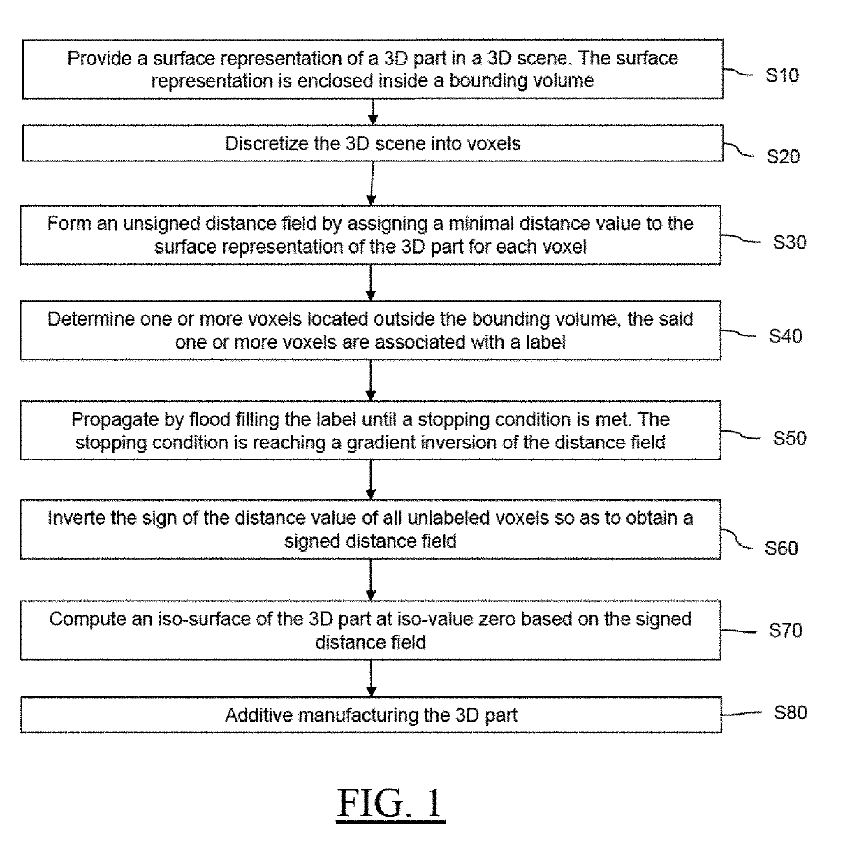
[0034]With reference to the flowchart of FIG. 1, it is proposed a computer-implemented method of additive manufacturing of a three-dimensional (3D) part. The method comprises providing a surface representation of a 3D part in a 3D scene. The surface representation of the 3D part is enclosed inside a bounding volume (BB). The method further comprises discretizing the 3D scene into voxels. Then, an unsigned distance field is formed by storing a minimal distance value to the surface representation of the 3D part for each voxel. Next, one or more voxels located outside the bounding volume are determined or identified. The one or more voxels located outside the bounding volume are associated with a label. Next, the label is propagated by flood filling until a stopping condition is met. The stopping condition is reaching a gradient inversion of the unsigned distance field. Then, the sign of the distance value of all unlabelled voxels is inverted. As a result, a signed distance field is ob...


PUM

PropertyMeasurementUnit
distanceaaaaaaaaaa
volumeaaaaaaaaaa
bounding volumeaaaaaaaaaa

Abstract

Described is a computer-implemented method of additive manufacturing of a three-dimensional (3D) part. The method includes obtaining a surface representation of a 3D part in a 3D scene, the surface representation being enclosed inside a bounding volume; discretizing the 3D scene into voxels, forming an unsigned distance field by storing a minimal distance value to the surface representation of the 3D part for each voxel, determining one or more voxels located outside the bounding volume, the one or more voxels located outside the bounding volume being associated with a label, propagating by flood filling the label until a stopping condition is met, which is reaching a gradient inversion of the distance field, inverting the sign of the distance value of all unlabeled voxels so as to obtain a signed distance field, computing an iso-surface of the 3D part at iso-value zero based on the signed distance field, and additive manufacturing the 3D part.

Description

CROSS-REFERENCE TO RELATED APPLICATIONS[0001]This application claims priority under 35 U.S.C. § 119 or 365 to European Application No. 17306558.2, filed Nov. 9, 2017. The entire contents of the above application(s) are incorporated herein by reference.FIELD OF THE INVENTION[0002]The invention relates to the field of computer programs and systems, and more specifically to a method, system and program for of additive manufacturing of a three-dimensional (3D) part.BACKGROUND[0003]A number of systems and programs are offered on the market for the design, the engineering and the manufacturing of objects. CAD is an acronym for Computer-Aided Design, e.g. it relates to software solutions for designing an object. CAE is an acronym for Computer-Aided Engineering, e.g. it relates to software solutions for simulating the physical behaviour of a future product. CAM is an acronym for Computer-Aided Manufacturing, e.g. it relates to software solutions for defining manufacturing processes and oper...

Claims


Application Information

Patent Timeline
Patent Type & Authority Applications(United States)
IPC IPC(8): B29C64/393G05B19/4099G06F17/50G06T17/20
CPCB29C64/393G05B19/4099G06F17/5086G06F17/5018G06T17/20G05B2219/49023B33Y50/02G06T17/00B29C64/386B33Y50/00G06F2119/18G06F30/00G06F2113/10G06F30/17G06F30/23
Inventor SCHMIDT, MARTIN-PIERRE
Owner DASSAULT SYSTEMES
Why Eureka
Try Eureka