Image forming apparatus and image forming method

Active Publication Date: 2019-05-09
FUJIFILM CORP
View PDF0 Cites 0 Cited by
  • Summary
  • Abstract
  • Description
  • Claims
  • Application Information

AI Technical Summary

Benefits of technology

The invention is about an image forming apparatus and method that can control the deformation of an image on a medium when tension is applied. The apparatus includes an image forming unit, a tension applying section, a transport unit, an image data acquisition section, an image forming liquid-application amount-information acquisition unit, a tension-information acquisition unit, an elastic modulus acquisition unit, an image conversion section, and an image formation control section. The apparatus can control the image size and accuracy when tension is applied to the medium. The invention provides an improved image forming apparatus and method that can control the deformation of an image on a medium when tension is applied.

Problems solved by technology

Accordingly, if the amount of deformation of a medium is changed in a case in which ink is applied to the medium, it is difficult to form an image that has a desired size at the time of use of the medium.
Accordingly, if the amount of deformation of a medium is changed in a case in which ink is applied to the medium, it is difficult to appropriately correct image data.
However, image formation using a medium that is deformed in a case in which tension is applied, that is, image formation in which the deformation of an image caused by the deformation of a medium causes a problem causes the same problems even in image formation in which a medium other than a fabric is used.

Method used


Image

  • Image forming apparatus and image forming method
  • Image forming apparatus and image forming method
  • Image forming apparatus and image forming method

Examples


first embodiment

[0078]

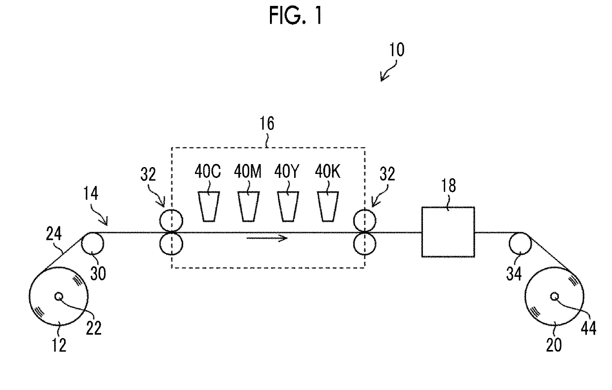
[0079]FIG. 1 is a diagram showing the overall configuration of an image forming apparatus according to a first embodiment. The ink jet recording apparatus 10 shown in FIG. 1 comprises a feed-side roll 12, a transport unit 14, an image forming unit 16, a post-treatment section 18, and a take-up roll 20.

[0080]In this embodiment, the ink jet recording apparatus in which an image is formed by an ink jet system is exemplified as an example of the image forming apparatus. Image formation described in this specification includes dyeing. An image described in this specification includes letters, numerals, or signs.

[0081]In the feed-side roll 12, a fabric 24 is wound on a core 22. The feed-side roll 12 is supported by a support member (not shown) so as to be rotatable about the core 22 serving as a rotating shaft. The feed-side roll 12 is one aspect of a medium feed unit.

[0082]The fabric 24 described in this specification includes a cloth or a textile in which two pieces of yarn are co...

second embodiment

[0312]Next, an image forming apparatus and an image forming method according to a second embodiment will be described. The difference of the second embodiment from the first embodiment will be mainly described in the description of the second embodiment. The description of the same components as the components of the first embodiment will be appropriately omitted in the second embodiment.

[0313]

[0314]FIG. 17 is a diagram showing the overall configuration of the image forming apparatus according to the second embodiment. The ink jet recording apparatus 10A shown in FIG. 17 includes a pretreatment section 15 shown in FIG. 17 in addition to the ink jet recording apparatus 10 shown in FIG. 1. The pretreatment section 15 comprises a treatment liquid head 40S.

[0315]The treatment liquid head 40S applies treatment liquid to an image forming surface of a fabric 24 by an ink jet system. The same structure as the structure of each of the ink jet heads 40C, 40M, 40Y, and 40K of the image forming...


PUM

PropertyMeasurementUnit
Coloraaaaaaaaaa
Lengthaaaaaaaaaa
Ratioaaaaaaaaaa

Abstract

There are provided an image forming apparatus and an image forming method in which the deformation of an image caused by the deformation of a medium is suppressed in the image formation on a medium to which tension is applied. The image forming apparatus includes an image forming liquid-application amount-information acquisition unit that acquires information about the amount of applied image forming liquid, a tension-information acquisition unit that acquires information about tension applied to a medium, an elastic modulus acquisition unit that acquires an elastic modulus of the medium calculated using the information about the amount of applied image forming liquid, a medium deformation amount-calculation unit that calculates the amount of deformation of the medium using tension information and the elastic modulus, and an image conversion section that converts the image data into converted image data, which represents a converted image to be formed on the medium in a state where the tension is applied. The image forming apparatus forms an image on the medium, to which the tension is applied, on the basis of the converted image data.

Description

CROSS-REFERENCE TO RELATED APPLICATIONS[0001]The present application is a Continuation of PCT International Application No. PCT / JP2017 / 022893 filed on Jun. 21, 2017 claiming priority under 35 U.S.C § 119(a) to Japanese Patent Application No. 2016-137762 filed on Jul. 12, 2016. Each of the above applications is hereby expressly incorporated by reference, in their entirety, into the present application.BACKGROUND OF THE INVENTION1. Field of the Invention[0002]The present invention relates to an image forming apparatus and an image forming method, and more particularly, to a technique for forming an image on a medium that is deformed due to the application of tension.2. Description of the Related Art[0003]An ink jet recording apparatus is known as an image forming apparatus that forms an image on a medium, such as paper or a film. The ink jet recording apparatus is also used to form an image on a medium, which is deformed at the time of application of tension, such as a fabric.[0004]In...

Claims


Application Information

Patent Timeline
IPC IPC(8): B41J2/14D06P5/30
CPCB41J2/14451D06P5/30B41J2/01B41J15/16B41J3/4078
Inventor WATANABE, HIROKI
Owner FUJIFILM CORP
Why Eureka
Try Eureka