
System and method for producing an image on an article

a technology of image content and article, applied in the field of printing system, can solve the problems of difficult adaptation of known printing techniques, such as 2d media printing technology, to apply image content to three-dimensional objects with non-uniform surfaces, and difficulty in adapting known printing techniques, such as 2d media printing technology, to achieve the effect of achieving uniform surfaces and avoiding problems such as affecting the quality of images

Active Publication Date: 2019-05-09
XEROX CORP
View PDF6 Cites 4 Cited by
  • Summary
  • Abstract
  • Description
  • Claims
  • Application Information

AI Technical Summary

Benefits of technology

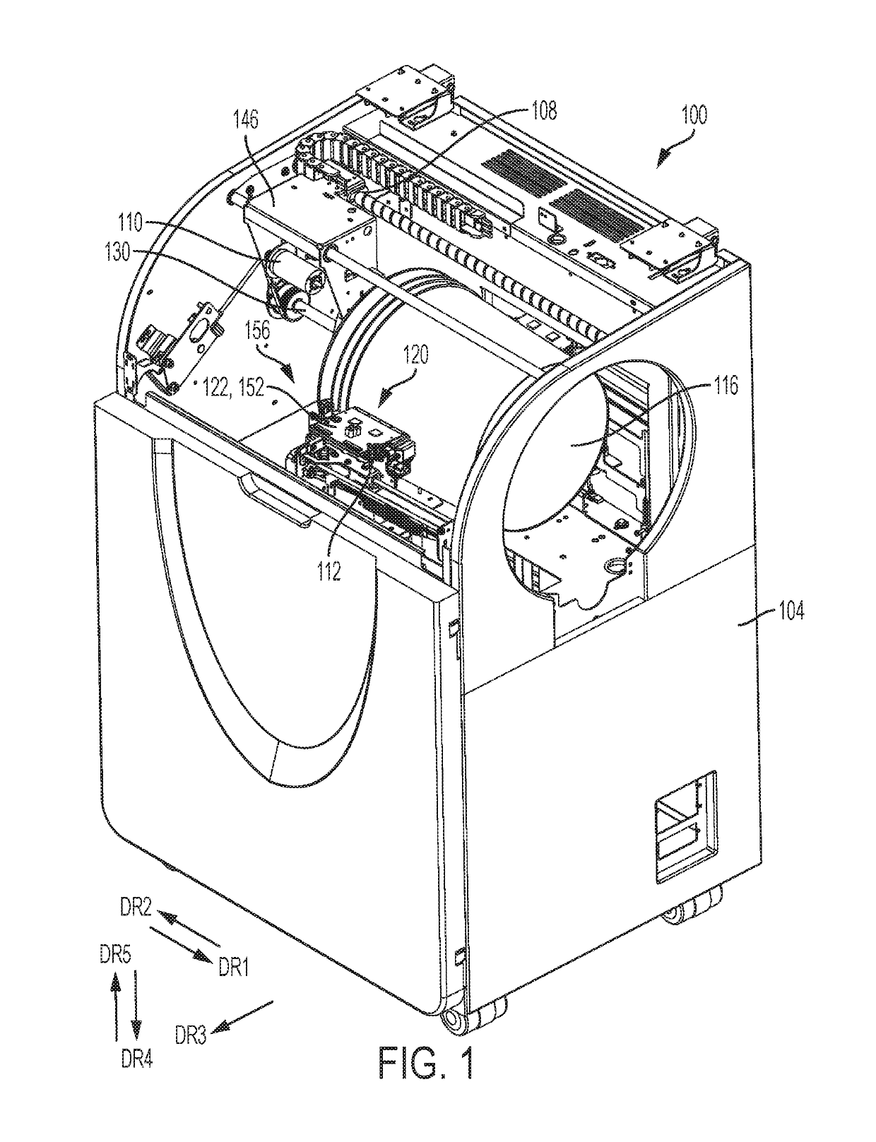
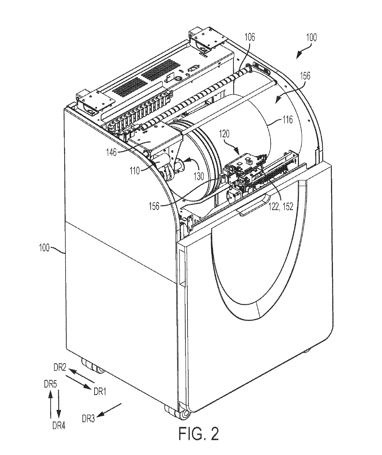
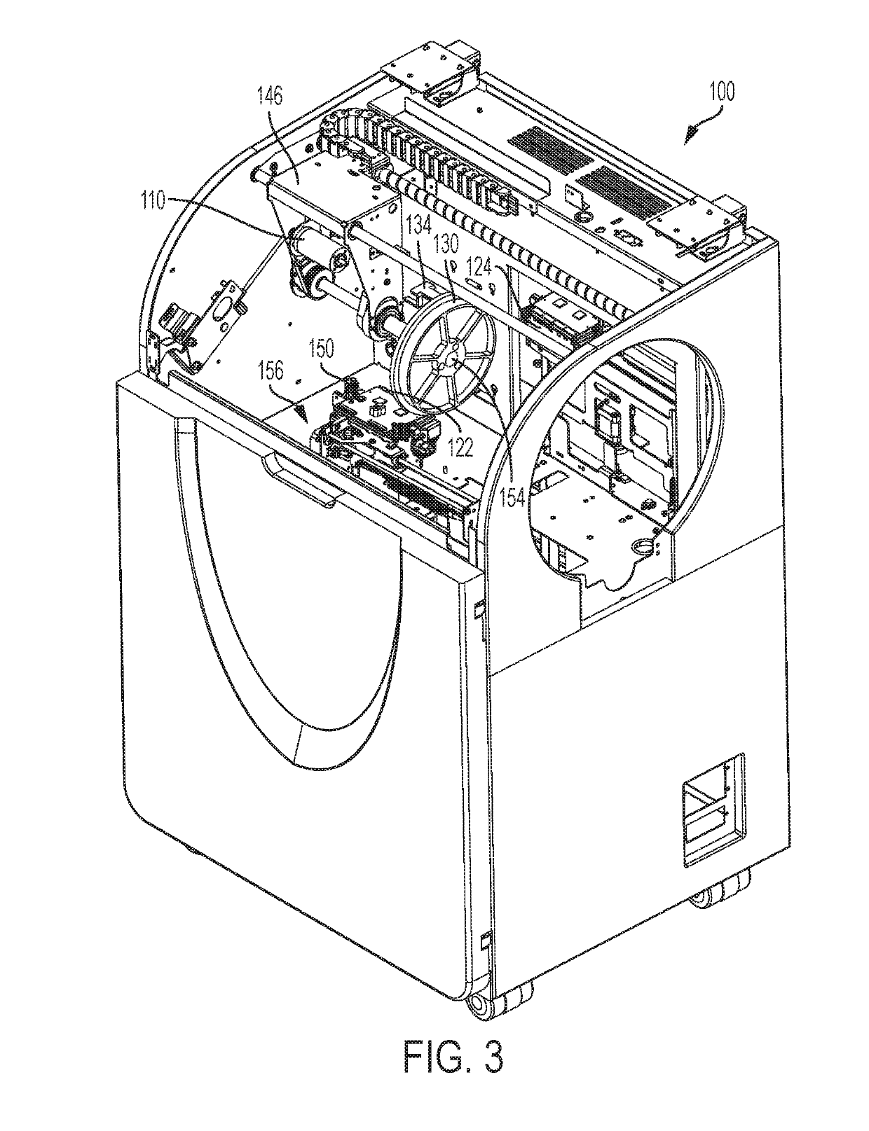
This patent describes a system and method for printing images onto objects using a vacuum, a spindle, and multiple printheads. The system includes a housing, a motor for rotating the spindle, and a controller for controlling the motion of the spindle and printheads. The method involves creating a negative pressure with a vacuum source and securing the object to a carrier that rotates in opposite directions. The object is then rotated using the first motor in each direction for a set distance, and the printheads are moved to a position based on the location of a protrusion on the object's surface. The method allows for precise printing of images onto objects.

Problems solved by technology

Ordering the correct number of products for each different logo to maintain sufficient inventory can be problematic and expensive.
Due to the proximity of the traversing printheads, these printers are limited to printing on surfaces that are relatively flat, i.e., with no protrusions.
Therefore, adapting known printing techniques, such as 2D media printing technology, to apply image content onto three-dimensional objects with non-uniform surfaces is difficult.
The difficulties are especially compounded when the objects are non-uniform in diameter, or contain large protrusions, e.g., the satellite rings or lip for attaching a lid on a bucket.

Method used


Image

  • System and method for producing an image on an article
  • System and method for producing an image on an article
  • System and method for producing an image on an article

Examples


Embodiment Construction

[0030]At the outset, it should be appreciated that like drawing numbers on different drawing views identify identical, or functionally similar, structural elements of the embodiments set forth herein. Furthermore, it is understood that these embodiments are not limited to the particular methodologies, materials and modifications described and as such may, of course, vary. It is also understood that the terminology used herein is for the purpose of describing particular aspects only, and is not intended to limit the scope of the disclosed embodiments, which are limited only by the appended claims.

[0031]Unless defined otherwise, all technical and scientific terms used herein have the same meaning as commonly understood to one of ordinary skill in the art to which these embodiments belong. As used herein, “full width”, e.g., “full width array sensor” and “full width printhead array”, is intended to be broadly construed as any structure that covers a significant width of the substrate. ...


PUM


Abstract

A system prints solid ink images on fibrous objects. The controller of the system is configured to operate a first motor to move an object rotating subsystem to and from a position opposite a plurality of printheads, to operate a second motor to rotate an object on a spindle of the object rotating subsystem at the position opposite the plurality of printheads, to operate a forced air heater to direct heated air onto a surface of the object as the object rotates at the position opposite the plurality of printheads, and to operate the plurality of printheads to eject a solid ink marking material onto the heated surface of the object as the object rotates in the first and / or second rotational direction. The solid ink image is affixed to the object by the heating of the object surface alone.

Description

CLAIM OF PRIORITY TO APPLICATIONS[0001]This patent application is a continuation-in-part application of and claims priority to U.S. patent application Ser. No. 15 / 945,367, which is entitled “System And Method For Producing An Image On An Article” and was filed on Apr. 4, 2018, which claims the benefit under 35 U.S.C. § 119(e) of U.S. Provisional Patent Application No. 62 / 562,116, which is entitled “System And Method For Producing An Image On An Article” and was filed Sep. 22, 2017, which application is incorporated herein by reference.TECHNICAL FIELD[0002]The presently disclosed embodiments are directed to a printing system that prints images directly on three-dimensional (3D) objects, and more particularly, to a system for printing directly on containers made of fibrous material, such as paper.BACKGROUND[0003]Commercial article printing typically occurs during the production of the article. For example, ball skins are printed with patterns or logos prior to the ball being completed...

Claims


Application Information

Patent Timeline
Patent Type & Authority Applications(United States)
IPC IPC(8): B41J3/407B41F13/004B41J29/38B41J11/00G03G15/22
CPCB41J3/4073B41F13/0045B41J29/38B41J11/002G03G15/224B41J29/02H04N1/0019B41J11/0022
Inventor LEO, MICHAEL F.CASEY, BRENDAN C.BUCHAR, WAYNE A.MCVEIGH, DANIEL J.
Owner XEROX CORP
Learn More