Display glasses using meta-surface planar lens

a planar lens and display device technology, applied in the field of optical lenses, can solve the problems of inconvenient wear on users, inability to see through most of the goggles, and inability to do anything else, so as to reduce the physical size of the display device

Active Publication Date: 2019-05-09
HU DARWIN
View PDF1 Cites 12 Cited by
  • Summary
  • Abstract
  • Description
  • Claims
  • Application Information

AI Technical Summary

Benefits of technology

[0020]One of the objects in the present invention is to have a display device integrated with such a planar lens to reduce the physical size of the display device.

Problems solved by technology

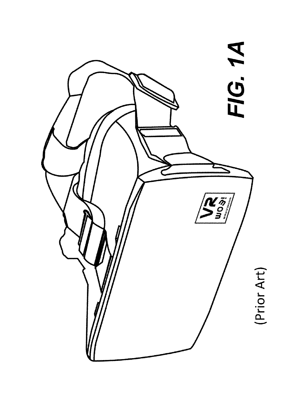
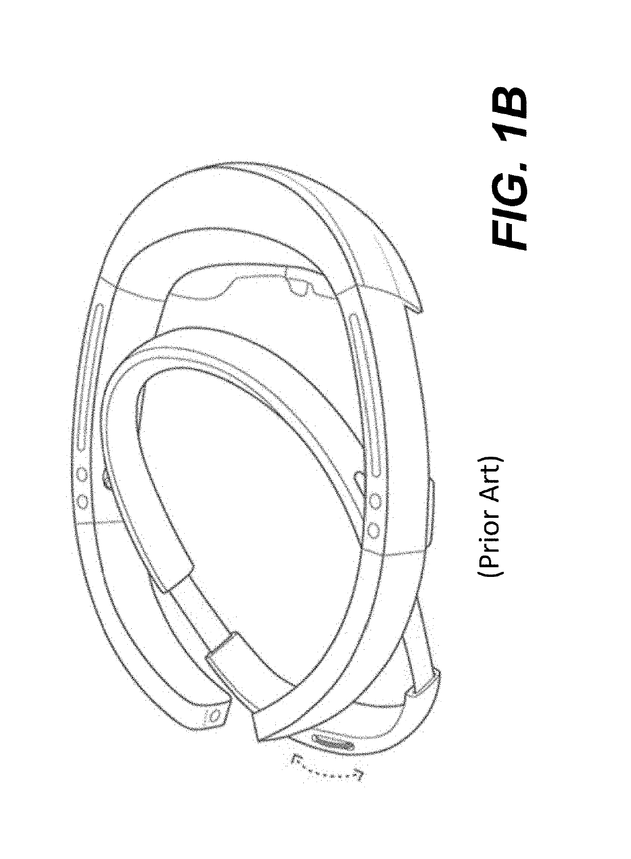
No matter how a goggle is designed, it appears bulky and heavy, and causes inconvenience when worn on a user.
Further most of the goggles cannot be seen through.
In other words, when a user wears a goggle, he or she would not be able to see or do anything else.
With such weight, a wearer won't feel comfortable when wearing it for a period.
Indeed, what is available in the market is generally heavy and bulky in comparison to normal glasses.
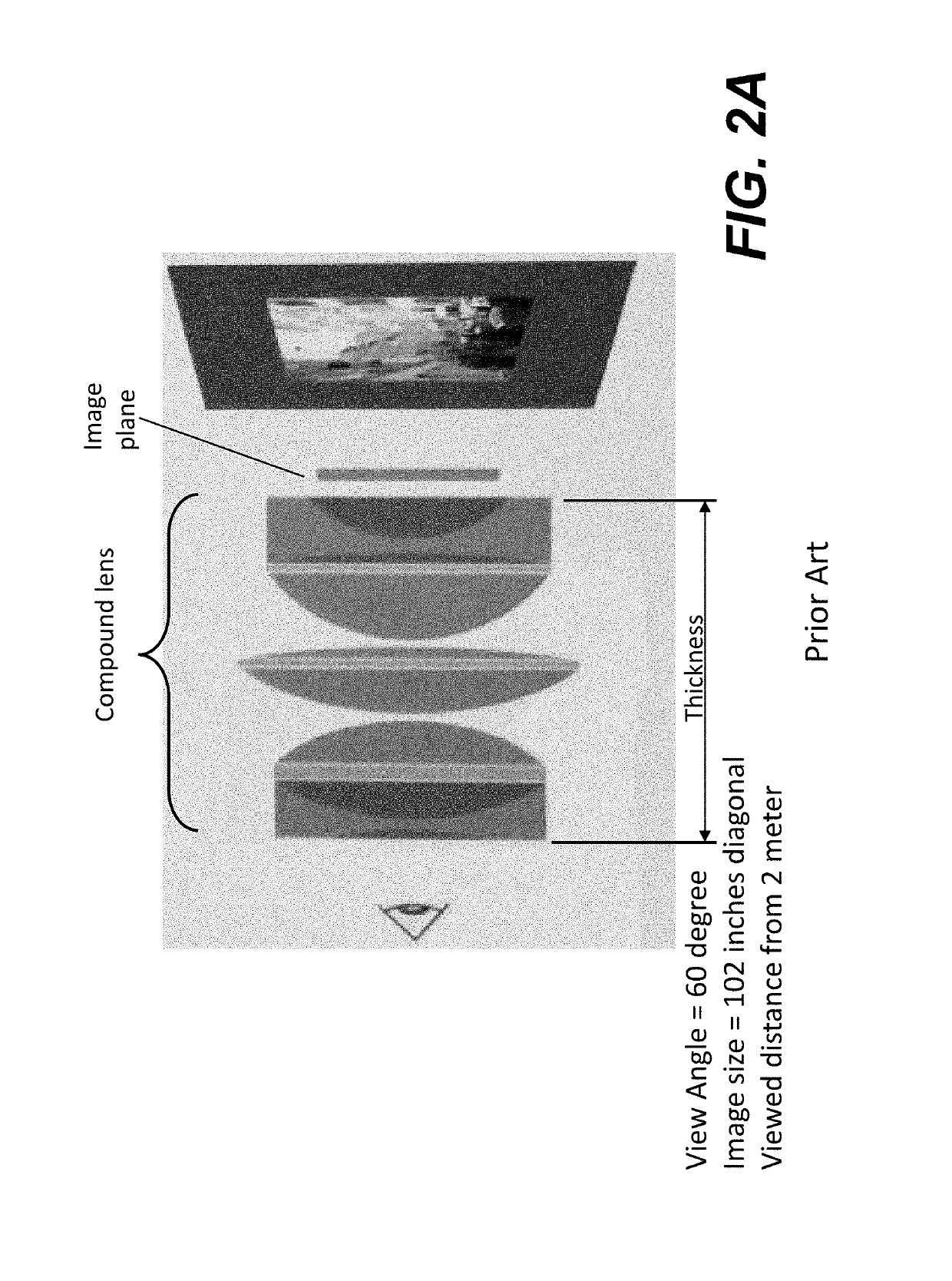
It can be appreciated that the compound lens of FIG. 2A, as most lenses in practical uses, are bulky and expensive.
As wearable or portable devices are getting smaller in sizes, the lenses for imaging or video are becoming a challenge to fit into such devices. FIG. 2B illustrates the use of a compound lens on iPhone X, where the lens has to stick out from the back of the device because of its relative bulky size of the compound lens in the phone.
In addition, the bulky size not only increases the lens cost, it also adds the weight.
Despite tremendous interest in planar lenses in the visible spectrum, there has been no solution that simultaneously satisfies the demands for high numerical aperture (NA) and efficiency, let alone for high end imaging applications.
However, as admitted by the group, it is still in the research phase, there are no such planar lenses available yet for commercial use.

Method used


Image

  • Display glasses using meta-surface planar lens
  • Display glasses using meta-surface planar lens
  • Display glasses using meta-surface planar lens

Examples


Embodiment Construction

[0038]The detailed description of the invention is presented largely in terms of procedures, steps, logic blocks, processing, and other symbolic representations that directly or indirectly resemble an optical lens. The description and representations herein are typically used by those skilled in the art to most effectively convey the substance of their work to others skilled in the art.

[0039]Reference herein to “one embodiment” or “an embodiment” means that a particular feature, structure, or characteristic described in connection with the embodiment can be included in at least one embodiment of the invention. The appearances of the phrase “in one embodiment” in various places in the specification are not necessarily all referring to the same embodiment, nor are separate or alternative embodiments mutually exclusive of other embodiments. Further, the order of blocks in process flowcharts or diagrams representing one or more embodiments of the invention do not inherently indicate any...


PUM


Abstract

Designs of display devices using one or more planar lenses are described. According to one aspect of the present invention, a planar lens includes at least a substrate and a plurality of nanosized studs. Depending on the implementation, the objects may be in different heights, spaced evenly or unevenly and oriented towards or outwards a focal point. When the planar lens is used with a lightguide guide that receives an image projected from a source, the image can be seen in the lightguide guide enlarged through the planar lens, provided that nanosized studs are properly structured, sized, oriented and arranged in a predefined pattern.

Description

BACKGROUND OF THE INVENTIONField of the Invention[0001]The present invention generally relates to the area of optical lens and more particularly relates to architecture and designs of optical lens using flat optical lens, where the optical lens is advantageously used in wearable display glasses for various applications including virtual reality augmented reality with 3D capabilities.Description of the Related Art[0002]Virtual Reality or VR is generally defined as a realistic and immersive simulation of a three-dimensional environment created using interactive software and hardware, and experienced or controlled by movement of the body. A person using virtual reality equipment is typically able to look around the artificially generated three-dimensional environment, moves around in it and interacts with features or items that are depicted on a screen or in goggles. Virtual realities artificially create sensory experiences, which can include sight, touch, hearing, and, less commonly, ...

Claims


Application Information

Patent Timeline
Patent Type & Authority Applications(United States)
IPC IPC(8): G02B27/01G02B27/14
CPCG02B27/0172G02B27/144G02B2027/0178G02B1/002G02B2027/015G02B2027/0152
Inventor HU, DARWIN
Owner HU DARWIN
Why Eureka
Try Eureka