Vertical Food Smoker

a smoker and vertical technology, applied in the field of smokers, can solve the problems of increasing the time needed to smoke food, heat loss, temperature drop, etc., and achieve the effect of minimizing heat loss

Active Publication Date: 2019-05-23
WIRTZ JERRY
View PDF4 Cites 4 Cited by
  • Summary
  • Abstract
  • Description
  • Claims
  • Application Information

AI Technical Summary

Benefits of technology

[0005]The present invention overcomes these shortcomings by providing an apparatus that allows a user to smoke foods using direct heat, minimizing heat loss during the restoking process, and up-flow smoke. The apparatus may consist of an upper smoking chamber with a door to access the food, a lower chamber with air intakes, a fire shield, and a firebox to accept the combustible materials. A user places the food in the smoke chamber, places combustible material in the firebox and ignites said material and uses the fire shield to control the airflow into the smoker and the temperature at which the food is smoked.

Problems solved by technology

The disadvantage to this design is that every time the smoker is opened, the temperature drops in proportion with the time the smokers is open, and this increases the time needed to smoke the food due to the temperature loss.
Smokers that do not require opening the smoking chamber but have another method for replenishing the smoking materials usually require the opening of a door which still results in heat loss though to a lesser extent than those that require opening the smoking chamber.
Current smoker designs allow airflow for the smoking process but do nothing to control and utilize the airflow to affect the smoking process.
The smokers that utilize ports for air intake typically do not protect the ports from falling debris and this debris may block and clog the ports thus leading to uneven air flow and uneven cooking.
The different smoker designs described above have significant disadvantages such as uneven cooking, time consuming operation and ultimately inefficient operation.

Method used


Image

  • Vertical Food Smoker
  • Vertical Food Smoker
  • Vertical Food Smoker

Examples


Embodiment Construction

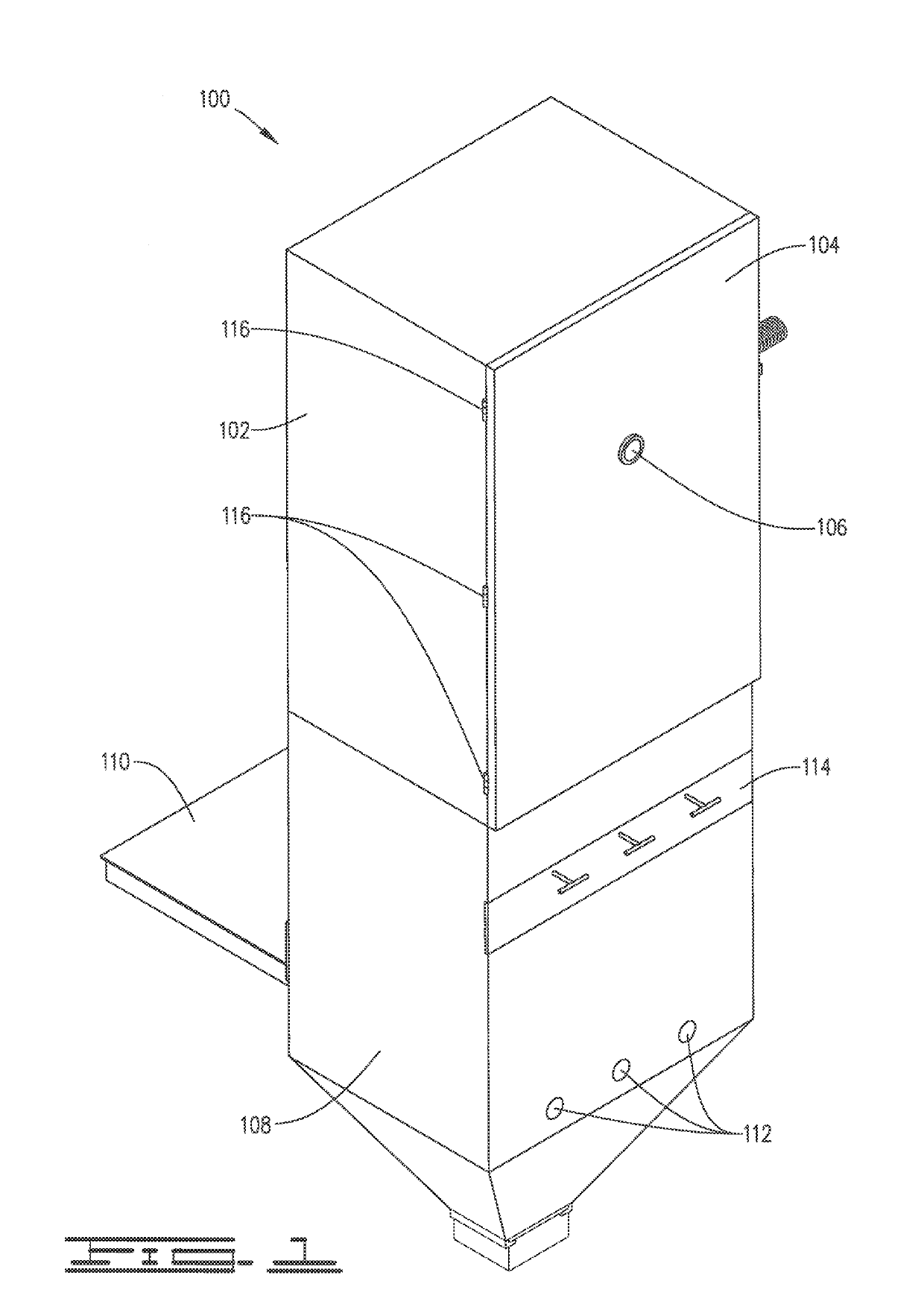
[0016]FIG. 1 is a perspective front view of the smoker 100. The smoker 100 may comprise a smoking chamber 102, a smoking chamber door 104, a temperature gauge 106, a lower chamber 108, an ember plate 110, an air intake 112, and a fire shield 114. In the preferred embodiment, the smoking chamber door 104 is hingedly attached with hinges 116 to the smoking chamber 102. A high temperature seal may be attached to the smoking chamber door 104 or to the smoking chamber 102 to maintain the inside temperature and prevent the smoke from escaping. The smoking chamber door 104 allows access to the interior of the smoking chamber 102 where foods that are desired to be smoked such as meats, cheeses and other types of foods are placed within the smoking chamber 102 on racks 302 for the smoking process. Affixed to the smoking chamber door 104 is a temperature gauge 106 to monitor the temperature inside the smoking chamber 102 without opening the smoking chamber door 104 and will also allow a user ...


PUM


Abstract

A smoker for imparting flavor to food comprising at least one smoking chamber, a lower chamber disposed below and in open communication with the bottom of smoking chamber, more than one flat, externally rotatable fire shield disposed below the support rack within the lower chamber, at least one firebox removably disposed within the lower chamber below the fire shields, the firebox having an outer door covering the firebox opening when the firebox is deployed inside the lower chamber, a handle, sidewalls and at least one bottom grate defining a support for a combustible material, slider means for supporting the firebox, an air intake below the firebox within the lower chamber, and an ember plate disposed outside of the lower chamber, whereby a combustible material is ignited in the firebox while disposed outside of the lower chamber, then pushed into the lower chamber to smoke the food.

Description

CROSS-REFERENCE TO RELATED APPLICATIONS[0001]None.FIELD OF THE INVENTION[0002]The invention generally relates to a smoker for smoke-curing meats and other foods. In particular, the invention relates to an apparatus for up-flow smoking with direct heat to smoke-cure the desired foods.BACKGROUND[0003]Many smokers use indirect heat and smoke to cure food. Indirect heat smokers require the smoking chamber to be opened to replenish the smoking material. The disadvantage to this design is that every time the smoker is opened, the temperature drops in proportion with the time the smokers is open, and this increases the time needed to smoke the food due to the temperature loss. Smokers that do not require opening the smoking chamber but have another method for replenishing the smoking materials usually require the opening of a door which still results in heat loss though to a lesser extent than those that require opening the smoking chamber. Current smoker designs allow airflow for the smok...

Claims


Application Information

Patent Timeline
Patent Type & Authority Applications(United States)
IPC IPC(8): A23B4/052A47J37/07
CPCA23B4/052A47J37/0704A47J37/0786A47J2037/0795A23B4/0523
Inventor WIRTZ, JERRY
Owner WIRTZ JERRY
Why Eureka
Try Eureka