Method for determining a position of at least one actuator

a technology of actuators and actuator positions, applied in the direction of hybrid vehicles, electrical control, machines/engines, etc., can solve the problems of actuators affecting the fuel consumption of engines, the position of at least one actuator is affected, and the fuel consumption is naturally increased, so as to optimize the fuel consumption and harmful emissions, improve the optimization effect, and reduce the effect of fuel consumption

Active Publication Date: 2019-05-23
VOLVO LASTVAGNAR AB
View PDF10 Cites 1 Cited by
  • Summary
  • Abstract
  • Description
  • Claims
  • Application Information

AI Technical Summary

Benefits of technology

[0009]An advantage of the present invention is that a prediction of future engine behavior is provided as an input when determining the actuator position for the at least one actuator. This will improve the optimization when controlling the actuators such that the respective parameters will have to sacrifice as little as possible which in turn will optimize fuel consumption and harmful emissions. By determining or predicting future engine behavior, transient control of the at least one actuator is improved by the method as the optimization will “know” future and upcoming engine behavior. The at least one second point in time can thus be composed of a plurality of future points in time such as e.g. a future time interval. The at least one second point in time may also in the following be referred to as the second point in time. It should be understood that the invention is not intended to, for example, reduce fuel consumption at all times, but rather to optimize the fuel consumption by taking into account other engine performance parameters. These other engine performance parameters are hence also optimized. Hereby, an optimization of the engine performance parameter values in relation to each other is achieved.
[0010]According to an example embodiment, the step of predicting the at least one engine performance parameter value at the at least one second point in time may be executed by the steps of predicting at least one of an engine torque and engine speed at the at least one second point in time; and determining the at least one engine performance parameter value at the at least one second point in time using the prediction of the at least one of engine torque and engine speed.
[0011]An advantage of predicting engine torque and / or engine speed at the at least one second, future point in time is that well defined input parameters for optimizing the position of the actuator is provided. Also, by means of a predicted engine torque and / or engine speed, it is possible to determine, either by means of e.g. calculations or further assumptions / predictions, the engine parameter values, which thus improves the accuracy of the optimization. Hereby, it is possible to prepare the engine for future working conditions at the second point in time.
[0012]According to an example embodiment, the actuator position may be determined by optimization of a weighted sum using the parameter values at the first point in time and the second point in time as input.
[0013]The weighted sum is beneficial since it provides for a relatively simple determination of which parameters to correlate, and how to correlate them, in order to achieve an optimization. By weighting the parameters, a respective weighting coefficient may be provided for each of the engine performance parameters desirable to obtain. The engine performance parameters are hence weighted such that the different engine performance parameters are comparable to each other to obtain a weighted sum.
[0014]According to an example embodiment, the actuator position of the at least one actuator may be associated with the at least one engine performance parameter. Hence, when e.g. increasing the exhaust thermal power of the internal combustion engine, the position of at least one actuator is affected.

Problems solved by technology

These requirements are often in contradiction to each other, i.e. when increasing the power of the engine, the fuel consumption is naturally also increased, and vice versa.
When for example determining an actuator position of an actuator controlling fuel injection, the openness degree of this specific actuator affects the fuel consumption of the engine.
Hence, when e.g. increasing the exhaust thermal power of the internal combustion engine, the position of at least one actuator is affected.
According to a non-limiting example, engine efficiency and pumping losses could be correlated to fuel consumption.

Method used


Image

  • Method for determining a position of at least one actuator
  • Method for determining a position of at least one actuator
  • Method for determining a position of at least one actuator

Examples


Embodiment Construction

[0058]The present invention will now be described more fully hereinafter with reference to the accompanying drawings, in which exemplary embodiments of the invention are shown. The invention may, however, be embodied in many different forms and should not be construed as limited to the embodiments set forth herein; rather, these embodiments are provided for thoroughness and completeness. Like reference character refer to like elements throughout the description.

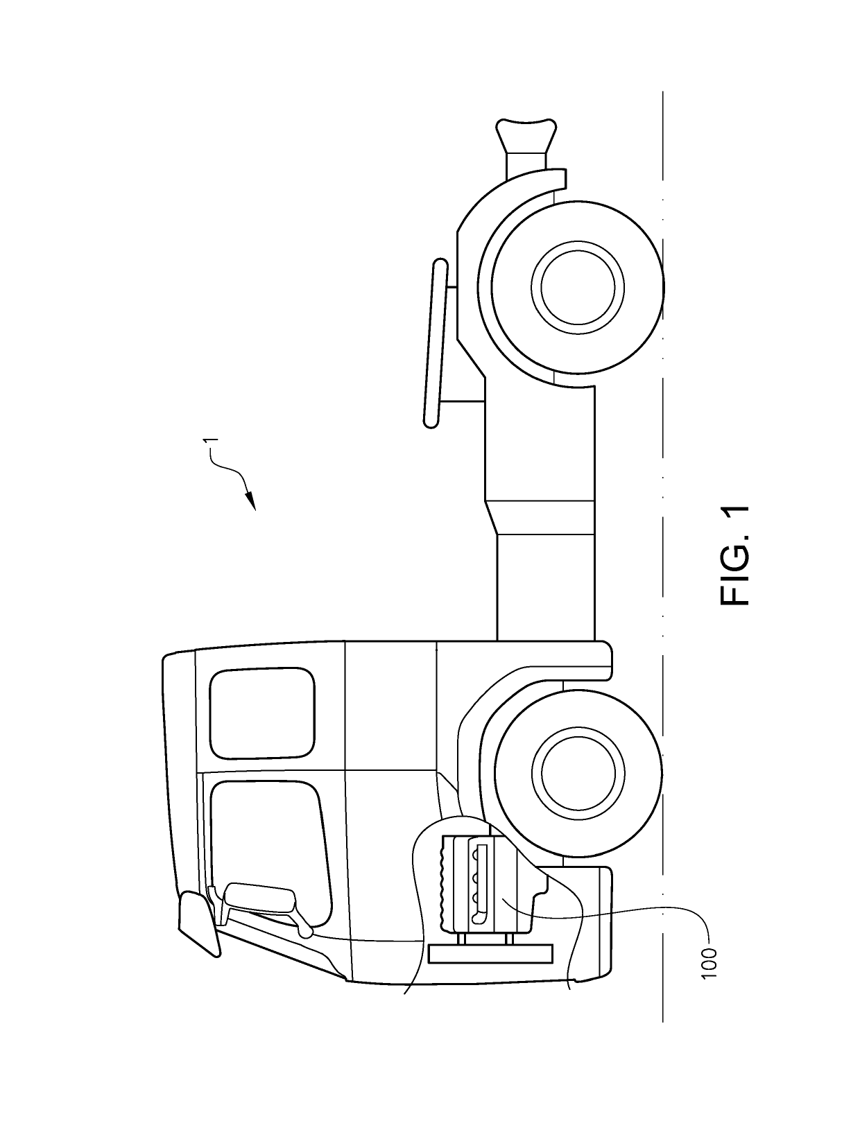
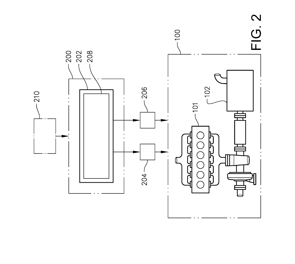
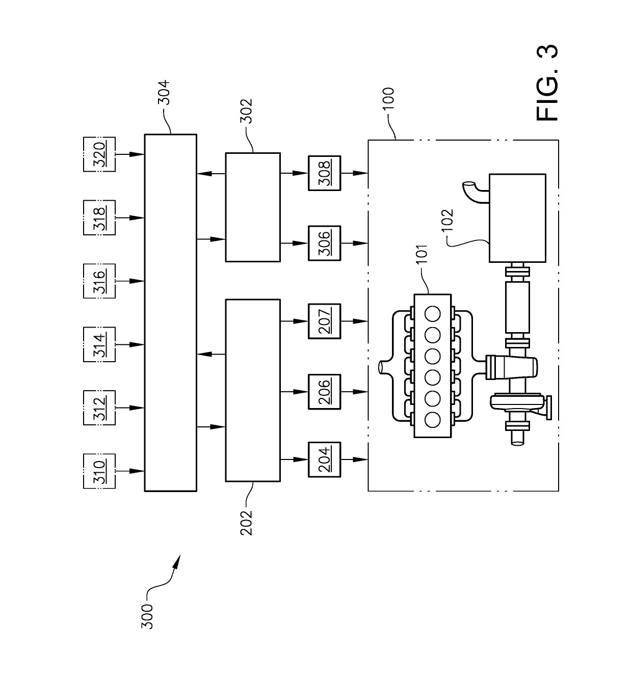
[0059]With particular reference to FIG. 1, there is provided a vehicle 1 comprising an internal combustion engine arrangement 100. In detail, the vehicle 1 is provided with a system (depicted in detail in FIGS. 2 and 3) for determining a position of at least one actuator according to an example embodiment of the present invention. The vehicle 1 depicted in FIG. 1 is a heavy duty vehicle, here in the form of a truck, for which the inventive system, which will be described further below, is particularly suitable for.

[0060]Refer...


PUM


Abstract

A method is provided for determining a position of at least one actuator of an internal combustion engine arrangement, the method including the steps of: receiving parameter values for engine performance parameters of the internal combustion engine arrangement at a first point in time; predicting at least one engine performance parameter value at an at least one second, future point in time; and determining an actuator position for the at least one actuator by an optimization using the parameter values at the first point in time and at the at least one second point in time as input.

Description

BACKGROUND AND SUMMARY[0001]The present invention relates to a method for determining a position of at least one actuator of an internal combustion engine arrangement. The invention also relates to a corresponding system for determining a position of at least one actuator of an internal combustion engine. The invention is applicable on vehicles, in particularly low, medium and heavy duty vehicles commonly referred to as trucks. Although the invention will mainly be described in relation to a truck, it may also be applicable for other type of vehicles such as e.g. working machines, cars, etc.[0002]In the field of vehicles, in particularly low-, medium- and heavy duty vehicles commonly referred to as trucks, performance and environmental requirements of the engines are continuously increasing due to e.g. local and regional emission legislations as well as a growing demand from the vehicle customers. Accordingly, there is often both a desire to increase the power of the engines as well...

Claims


Application Information

Patent Timeline
Patent Type & Authority Applications(United States)
IPC IPC(8): F02D41/14F02D41/02F01N9/00
CPCF02D41/1406F02D41/0235F01N9/00F02D2041/1412F02D2200/0625F02D2200/0802F02D2200/021F02D2200/602F02D2200/701F02D2250/36F01N2560/06F01N2900/08F01N2900/12F01N2900/1602B60W20/11
Inventor GELSO, ESTEBANDAHL, JOHAN
Owner VOLVO LASTVAGNAR AB
Why Eureka
Try Eureka