Method for the Speed Synchronization of a Crane Drive and Crane Drive

Active Publication Date: 2014-09-25
LIEBHERR WERK EHINGEN
View PDF5 Cites 4 Cited by
  • Summary
  • Abstract
  • Description
  • Claims
  • Application Information

AI Technical Summary

Benefits of technology

The present invention aims to reduce fuel consumption and noise emission in a crane. One solution is to unlock the mechanical drive train when the crane is in an idle mode. This helps to minimize power loss and waiting times. Another approach is to automatically shut off the drive unit when the crane is not in use. These solutions provide efficiency and flexibility for crane operations.

Problems solved by technology

Typically the operator of the crane does not know the requisite motor speed that is necessary to correctly operate the hydraulic power system of the crane at the desired motion speed.
This situation leads not only to an excessive fuel consumption and high noise emission, but also to an unnecessarily high accelerated wear of the drive unit.

Method used


Image

  • Method for the Speed Synchronization of a Crane Drive and Crane Drive
  • Method for the Speed Synchronization of a Crane Drive and Crane Drive
  • Method for the Speed Synchronization of a Crane Drive and Crane Drive

Examples


case 1

[0062]

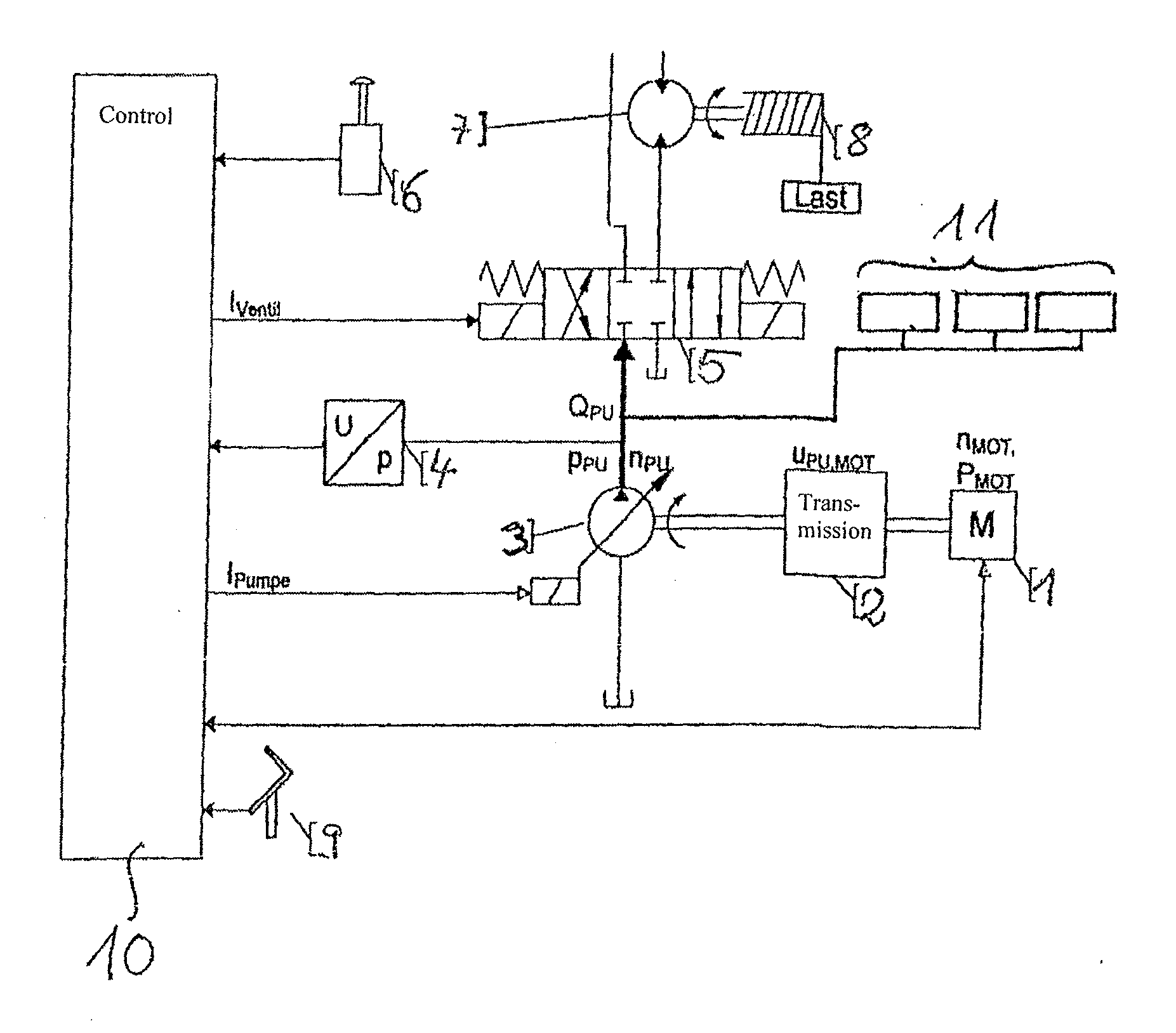
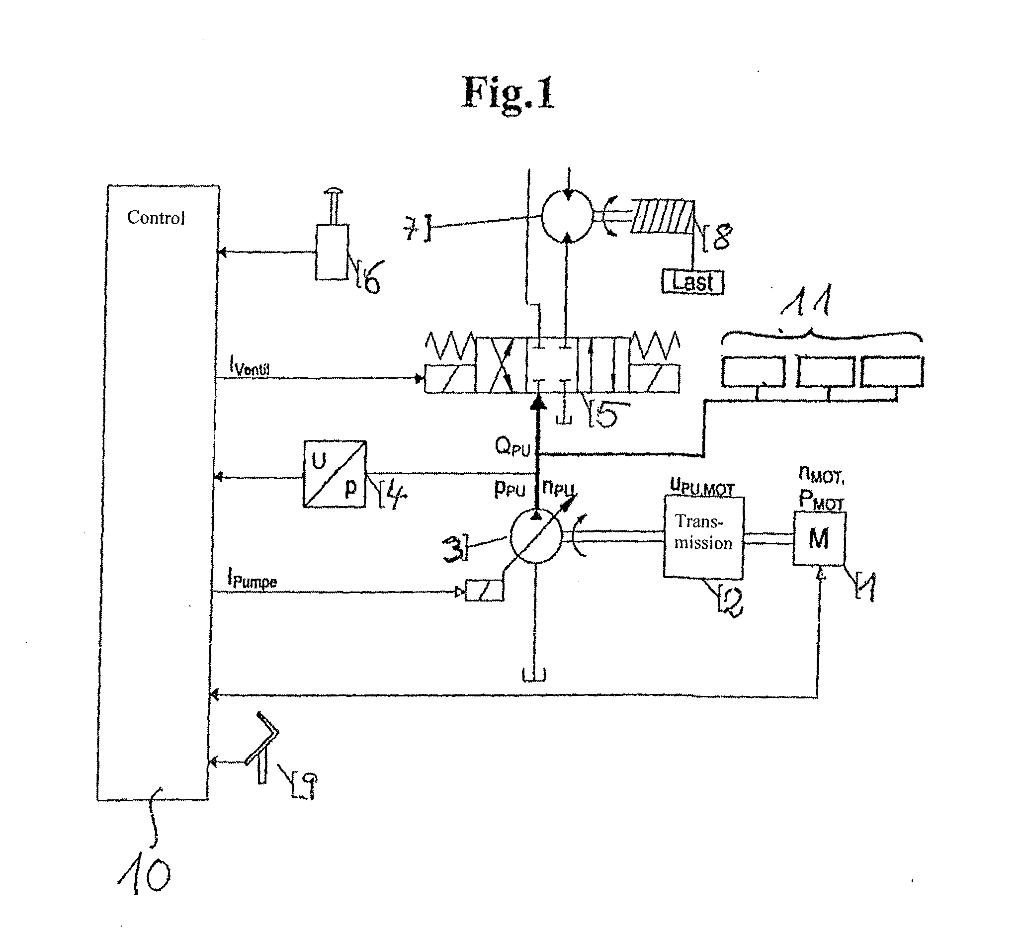
[0063]The crane control system 10 determines the volumetric flow rate QFahrer requested by the operator. The motor speed nMOT is changed until QPU1 matches the volumetric flow rate requested by the operator QFahrer. Then the crane control system 10 computes the volumetric flow rate QPU2, based on the instantaneous motor output power PMOT and the pump pressure pPU. In the case of the hydraulic motor 7 with no load, QPU2 is greater than QPU1. This means that sufficient motor output power PMOT is on hand to fulfill the condition from equation 6, and that an additional increase in the motor speed nMOT is not necessary.

case 2

[0064]

[0065]In the case of a hydraulic motor 7 with a load, the following applies. The crane control system 10 determines the volumetric flow rate QFahrer requested by the operator. The motor speed nMOT is changed until QPU1 matches the volumetric flow rate requested by the operator QFahrer. Then the crane control system 10 computes the volumetric flow rate QPU2, based on the instantaneous motor output power PMOT and the pump pressure pPU. Since the loaded hydraulic motor 7 generates a counter torque to the drive torque of the drive motor 1, the result in this case is a volumetric flow rate QPU2 that is less than QPU1. The provided motor output power PMOT is insufficient to fulfill the condition from equation 6. Since the motor output power PMOT also increases as the motor speed nMOT increases, an additional increase in the motor speed nMOT is necessary.

[0066]Therefore, the method according to the invention provides the following steps:[0067]1. The crane control system 10 determines...


PUM


Abstract

A method is used for synchronizing the speed of a hydraulic crane drive having at least one hydraulic consumer, which is fed with a variable volumetric rate of flow by way of at least one hydraulic variable displacement pump. The at least one hydraulic variable displacement pump is driven by way of a drive unit of the crane. By way of the crane control system, a swashplate angle of the at least one variable displacement pump is open and / or closed loop controlled as a function of the demanded volumetric flow rate for at least one consumer and / or on the basis of one additional parameter.

Description

BACKGROUND OF THE INVENTION[0001]The present invention relates to a method for synchronizing the speed of a hydraulic crane drive comprising at least one hydraulic consumer, for example a hydraulic motor, that is fed by means of at least one hydraulic variable displacement pump, and in which the at least one variable displacement pump is driven by means of the drive unit of the crane.[0002]A crane, and in particular a mobile crane, has a hydraulic power system for driving the various crane functions. This hydraulic power system is supplied by one or more hydraulic pumps, which are supplied at least in part by means of a central drive unit of the crane, such as an internal combustion engine. The delivery volume of the individual hydraulic pumps depends on the drive speed of the motor output. The greater the delivered pump volume is, the faster is the motion speed of the individual hydraulic consumers, which are fed by means of the pump, in order to carry out the various functions of ...

Claims


Application Information

Patent Timeline
IPC IPC(8): B66C13/20
CPCB66C13/20
Inventor KISSELBACH, ALEXANDER
Owner LIEBHERR WERK EHINGEN
Why Eureka
Try Eureka