
Method for determining the instant at which a nitrogen oxide storage catalyst is switched from the storage phase to the regeneration phase and for diagnosing the storage properties of this catalyst

Inactive Publication Date: 2010-06-15
UMICORE AG & CO KG
View PDF25 Cites 0 Cited by
  • Summary
  • Abstract
  • Description
  • Claims
  • Application Information

AI Technical Summary

Benefits of technology

[0012]It is an object of the present invention to improve the accuracy with which the instant at which a nitrogen oxide storage catalyst is switched from the storage phase to the regeneration phase is determined and thereby to open up the possibility of further optimizing the fuel consumption when operating a nitrogen oxide storage catalyst while, at the same time, maintaining low nitrogen oxide emissions. Moreover, the invention is also to provide a possibility for on board diagnosis of the performance of the nitrogen oxide storage catalyst.

Problems solved by technology

One problem with these engines is the removal of the nitrogen oxides formed during combustion from the lean exhaust gas.
On account of the high oxygen content of the lean exhaust gas, it is very difficult to reduce the nitrogen oxides to nitrogen and thereby to render them harmless.
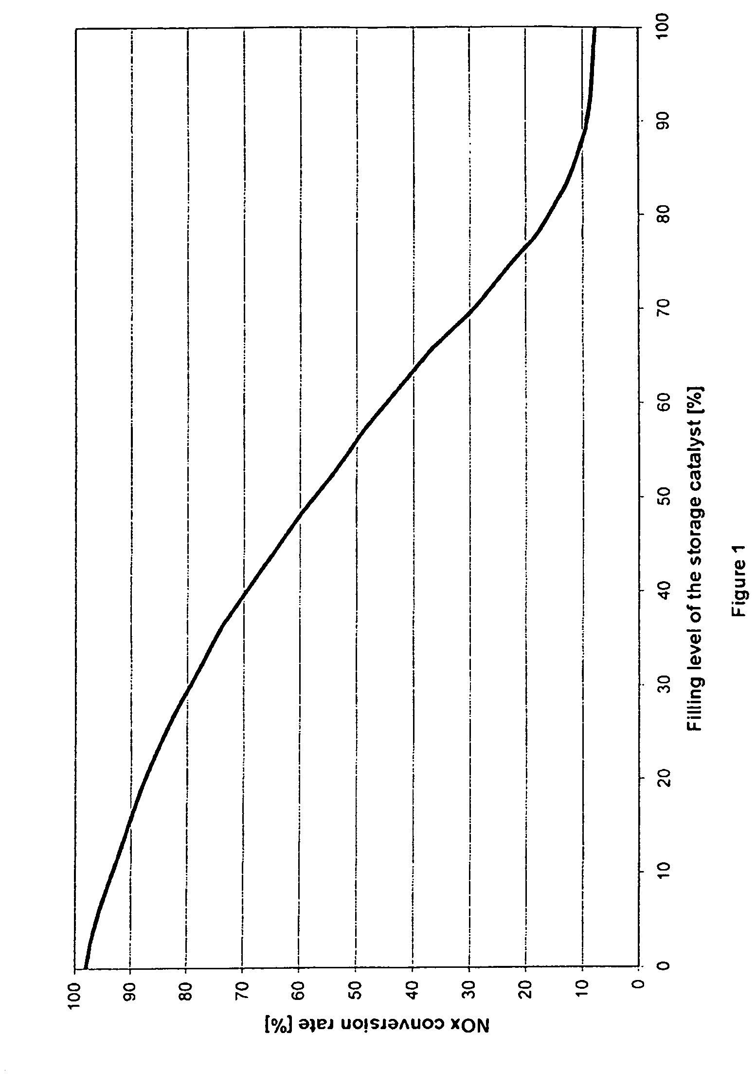
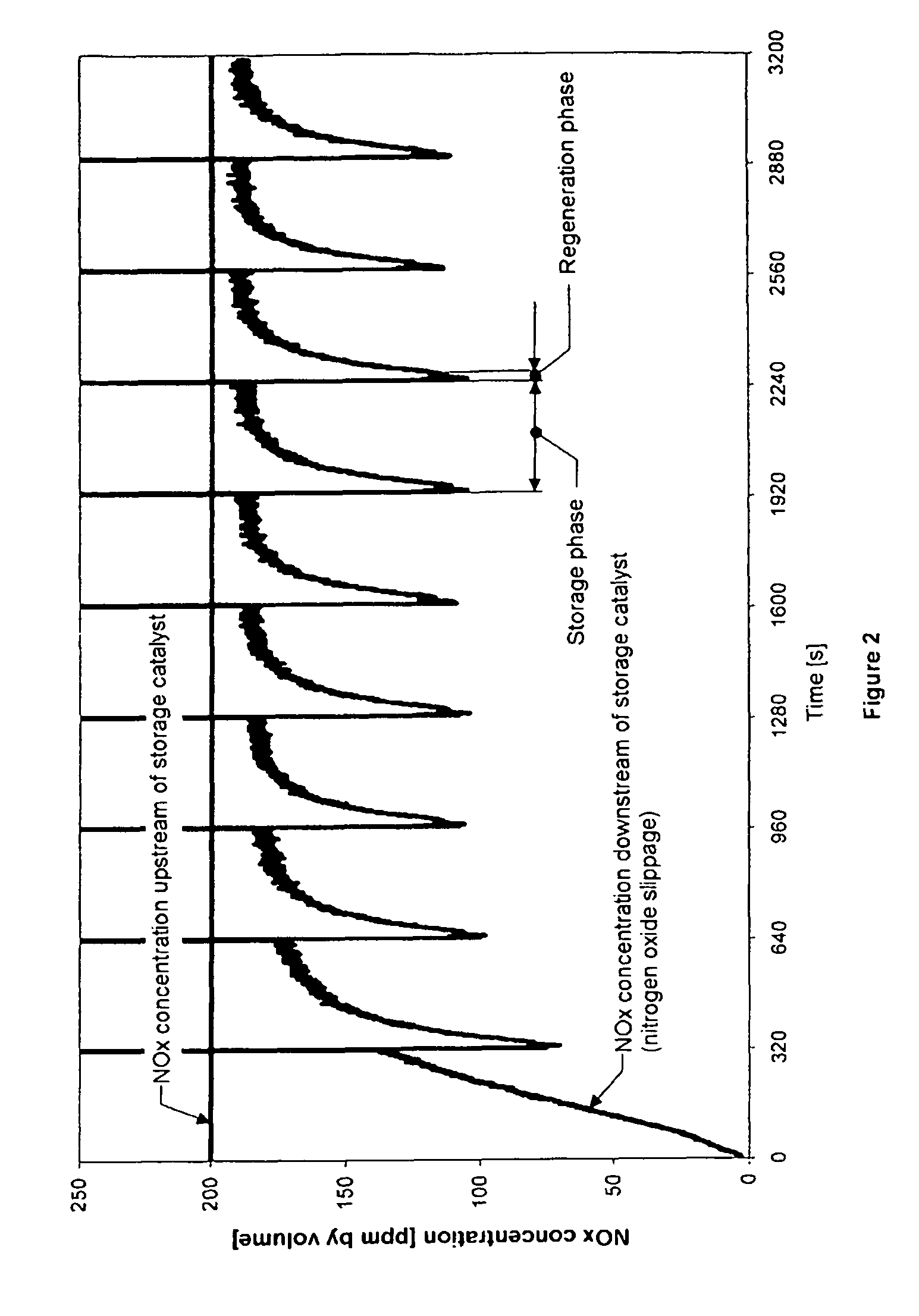
Since a nitrogen oxide storage catalyst of this type has only a limited storage capacity, it has to be regenerated from time to time, i.e. the stored nitrogen oxides have to be released again and reduced to form nitrogen.
The required, regular regeneration of the storage catalyst limits the maximum saving on fuel consumption which can be achieved with a lean-burn engine.
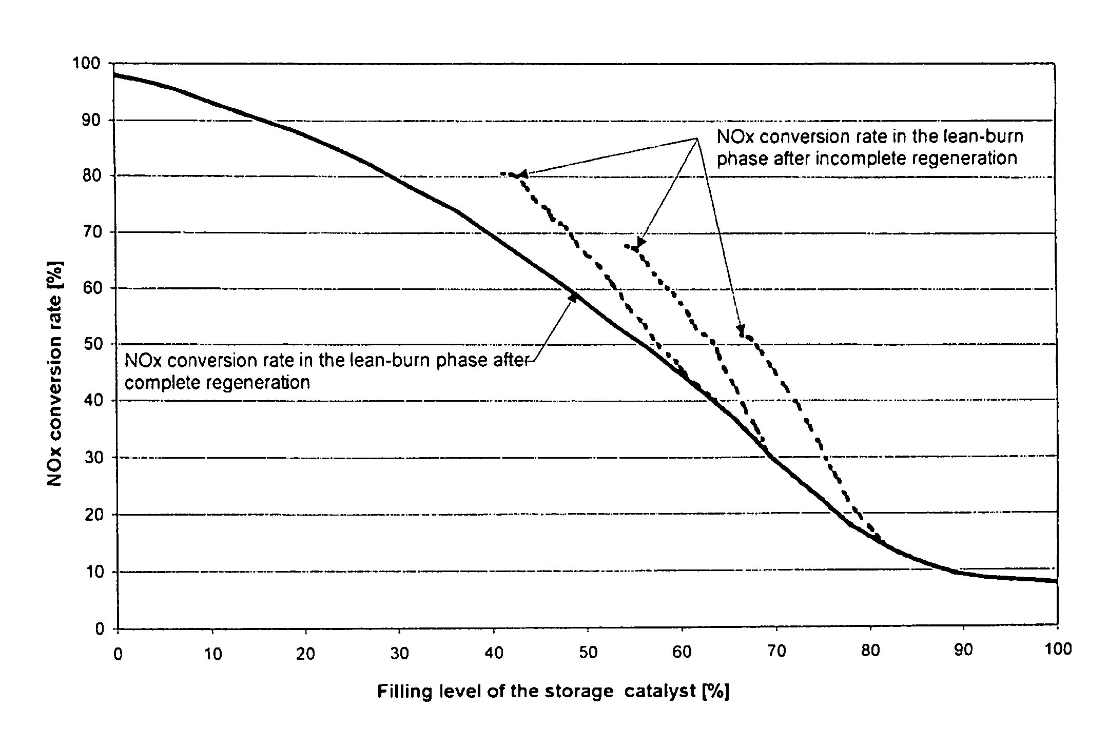
If the limit filling level is selected to be a low one, the residual emissions of nitrogen oxides which still remain are low, but the fuel consumption is undesirably increased as a result of the frequent regeneration.
Moreover, there is a risk of the defined limit filling level being exceeded more frequently on account of inaccurate determination of the current filling level, which further increases the remaining nitrogen oxide emissions.
In addition to the problem of determining the optimum instant to switch from the storage phase to the regeneration phase, it is also necessary to monitor the increasing storage capacity with increasing operating time (aging) of the storage catalyst.
Therefore, they reduce the nitrate storage capacity to an increasing extent.
The permanent aging of a storage catalyst is related to thermal damage to the component of the storage catalyst.
Overheating causes the storage materials themselves and also the catalytically active precious metals to sinter together, so that they lose active surface area.

Method used


Image

  • Method for determining the instant at which a nitrogen oxide storage catalyst is switched from the storage phase to the regeneration phase and for diagnosing the storage properties of this catalyst
  • Method for determining the instant at which a nitrogen oxide storage catalyst is switched from the storage phase to the regeneration phase and for diagnosing the storage properties of this catalyst
  • Method for determining the instant at which a nitrogen oxide storage catalyst is switched from the storage phase to the regeneration phase and for diagnosing the storage properties of this catalyst

Examples


example

[0042]A conventional storage catalyst was produced by coating a honeycomb carrier of cordierite (62 cells / cm2, corresponding to 400 cpsi) with a catalyst material based on barium oxide, which as catalytically active components contained platinum and rhodium on an active alumina.

[0043]A drilled core of this catalyst with a diameter of 2.54 cm and a length of 7.62 cm was used for the following tests in a model gas installation. In the model gas installation, the catalyst was subjected to various working cycles comprising storage and regeneration phases at a gas temperature of 250° C. and a space velocity of 77 000 h−1. The gas compositions during these phases can be taken from the table below. Under these exhaust-gas conditions, the catalyst had a storage capacity of approximately 2.5 grams of NO2 per liter of catalyst volume.

[0044]

TABLEGas composition during storage and regeneration phaseStorage phaseRegeneration phaseGas component(lean)(rich)Carbon monoxide200ppm by volume2%by volum...


PUM


Abstract

When a nitrogen oxide storage catalyst is being regenerated, the regeneration may be terminated for example as a result of a premature load change in the engine, which can lead to incomplete emptying of the storage catalyst. The residual filling level which remains in the catalyst following an incomplete regeneration of this nature is used as the starting value for calculation of the filling level during the next storage phase. After incomplete regeneration, the nitrogen oxide conversion rate is initially greater than would be expected, on account of the residual filling level. By taking this increased conversion rate into account when calculating the filling level during the storage phase, it is possible to further improve the accuracy of the calculation.

Description

FIELD OF THE INVENTION[0001]The present invention relates to the exhaust-gas purification of internal combustion engines which are operated predominantly with a lean air / fuel ratio, known as lean-burn engines, including diesel engines and lean-burn gasoline engines. Lean-burn engines were developed to reduce fuel consumption. They should ideally save up to 25% of the fuel.BACKGROUND OF THE INVENTION[0002]One problem with these engines is the removal of the nitrogen oxides formed during combustion from the lean exhaust gas. Depending on the operating state of the engine, the nitrogen oxides emitted by these engines comprise from 60 to 95% by volume of nitrogen monoxide. On account of the high oxygen content of the lean exhaust gas, it is very difficult to reduce the nitrogen oxides to nitrogen and thereby to render them harmless. One possible way of removing the nitrogen oxides consists in purifying the exhaust gases with the aid of a nitrogen oxide storage catalyst.[0003]Nitrogen ox...

Claims


Application Information

Patent Timeline
IPC IPC(8): F01N3/00B01D53/94B01D53/96F01N3/08F01N11/00
CPCB01D53/9495F01N3/0871F01N3/0885F01N11/005Y02T10/47F01N2430/06F01N2550/03Y02T10/20Y02T10/12Y02T10/40
Inventor VOTSMEIER, MARTINKLUGE, JULIANEGOEBEL, ULRICHGIESHOFF, JURGENKREUZER, THOMAS
Owner UMICORE AG & CO KG
Learn More