Vehicle and power control system

Active Publication Date: 2019-05-30
TOYOTA JIDOSHA KK
View PDF5 Cites 3 Cited by
  • Summary
  • Abstract
  • Description
  • Claims
  • Application Information

AI Technical Summary

Benefits of technology

[0006]The present disclosure has been made to solve such a problem, and has an object to suppress a power storage device from havin

Problems solved by technology

However, if the power stored in the in-vehicle power storage device is supplied to outside the vehicle (for example, to the system power supply) without a plan, the power storage devic

Method used


Image

  • Vehicle and power control system
  • Vehicle and power control system
  • Vehicle and power control system

Examples


Example

First Embodiment

[0038]

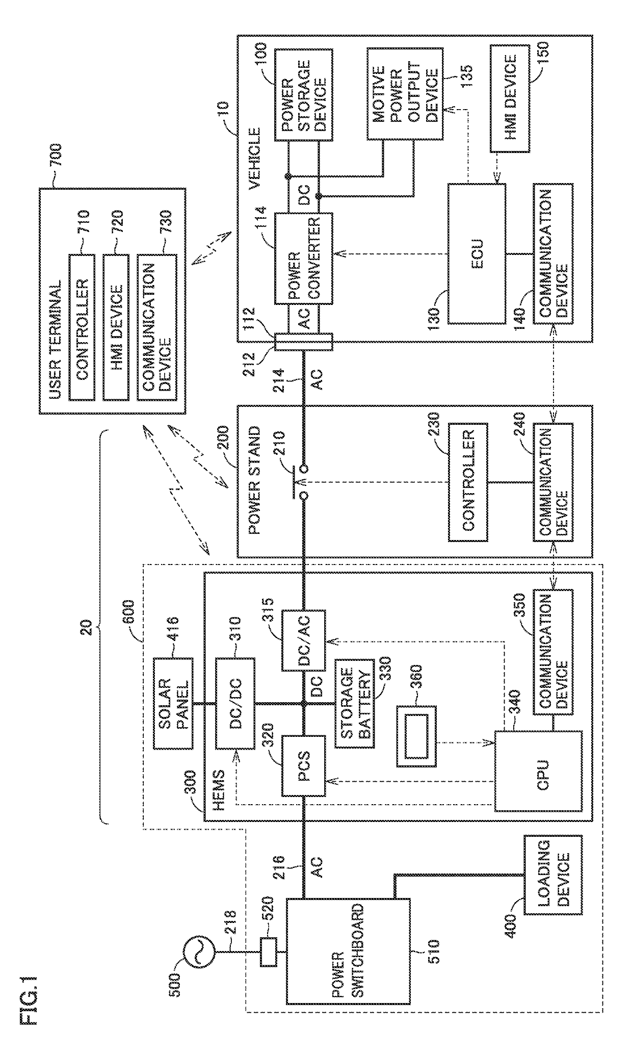
[0039]FIG. 1 schematically shows an entire configuration of a power system including a vehicle according to a first embodiment. The power system includes a vehicle 10, a power facility 20, a loading device 400, a commercial system power supply 500, a power switchboard 510, and a user terminal 700. Power facility 20 includes a power stand 200, a HEMS (Home Energy Management System) 300, and a solar panel 416.

[0040]HEMS 300, loading device 400, solar panel 416, and power switchboard 510 are provided in a house 600.

[0041]Vehicle 10 is an electrically powered vehicle configured to generate driving power for traveling using electric power and to exchange electric power with power stand 200. It should be noted that the configuration of the electrically powered vehicle is not particularly limited as long as the electrically powered vehicle can travel using electric power. Examples of vehicle 10 include a hybrid vehicle, an electric vehicle, and the like.

[0042]Vehicle ...

Example

Second Embodiment

[0125]In this second embodiment, when power facility 20 is configured to not only supply power to vehicle 10 but also receive power from vehicle 10 as in the power system shown in FIG. 1, the SOC is permitted to transitionally (temporarily) exceed the upper limit SOC in vehicle 10 while vehicle 10 is connected to power facility 20.

[0126]Accordingly, when surplus power (for example, a surplus of power generated by solar panel 416) is generated at the power facility 20 side, the surplus power can be temporarily stored in vehicle 10 without wasting the surplus power, and when power demand of power facility 20 is then increased, the power stored in vehicle 10 can be returned to power facility 20.

[0127]The entire configuration of the power system in this second embodiment is the same as that of the power system shown in FIG. 1 according to the first embodiment.

[0128]FIG. 8 shows an exemplary change in SOC with passage of time in the second embodiment. FIG. 8 corresponds ...


PUM


Abstract

A vehicle includes a power storage device, a connector, a power converter, and an ECU. The connector and the power converter are configured to supply, to the power facility, power stored in the power storage device. When the vehicle is connected to the power facility via a power cable, the ECU is configured to control an upper limit SOC and a lower limit SOC in association with time. The upper limit SOC and lower limit SOC define an SOC usable range of the power storage device.

Description

CROSS-REFERENCE TO RELATED APPLICATIONS[0001]This nonprovisional application claims priority to Japanese Patent Application No. 2017-225964 filed on Nov. 24, 2017, with the Japan Patent Office, the entire contents of which are hereby incorporated by reference.BACKGROUNDField[0002]The present disclosure relates to a vehicle and a power control system, particularly, a vehicle configured to exchange power with a power facility provided outside the vehicle, as well as a power control system.Description of the Background Art[0003]Japanese Patent No. 5123419 discloses a vehicle configured to exchange power with a power facility provided outside the vehicle. In this vehicle, a power storage device mounted on the vehicle can be charged from the power supply facility by connecting, to an inlet of the vehicle, a charging connector for connecting the vehicle to the power supply facility external to the vehicle. On the other hand, by connecting, to the inlet, a power supplying connector for con...

Claims


Application Information

Patent Timeline
IPC IPC(8): B60L11/18H02J7/35
CPCB60L11/1862B60L11/1816B60L11/1842H02J7/35B60L53/14B60L55/00B60L58/13H02J2310/48H02J2310/12H02J7/007Y02T90/12Y04S10/126Y02E60/00H02J7/02H02J7/0048H02J3/322H02J7/00304Y04S30/12Y02T90/167Y02T10/70Y02T10/7072
Inventor ICHIKAWA, SHINJI
Owner TOYOTA JIDOSHA KK
Why Eureka
Try Eureka