Fuel cell system, control method of fuel cell system, and computer program

Active Publication Date: 2019-07-18
BROTHER KOGYO KK
View PDF0 Cites 2 Cited by
  • Summary
  • Abstract
  • Description
  • Claims
  • Application Information

AI Technical Summary

Benefits of technology

[0003]Some of fuel cell systems that obtain electromotive force by an electrochemical reaction of hydrogen and oxygen are provided with a hydrogen circulation passage through which anode waste gas discharged from an anode of a fuel cell stack is circulated, so that residual hydrogen included in the anode waste gas is effectively used. Regarding such a fuel cell system, anode waste gas includes impurities such as nitrogen or water vapor, and therefore the concentration of such impurities may possibly increase at an anode, the hydro

Problems solved by technology

Regarding such a fuel cell system, anode waste gas includes impurities such as nitrogen or water vapor, and therefore the concentration of such impurities may possibly increase at an anode, the hydrogen concentration may possibly relatively decrease, and the performance of the fuel cell stack may possibly deteriorate as the anode waste gas is circulated and power generation is continued.
When generated water passes through an electrolyte membrane under osmotic pressure or a concentration difference, infiltrates to the anode side, and is stored on the anode side, a so-called flooding phenomenon in which water stays may possibly occur, and the power generation performance of the fuel cell stack may possib

Method used


Image

  • Fuel cell system, control method of fuel cell system, and computer program
  • Fuel cell system, control method of fuel cell system, and computer program
  • Fuel cell system, control method of fuel cell system, and computer program

Examples


Example

[0019]The following description will explain First Embodiment of the present invention with reference to the drawings.

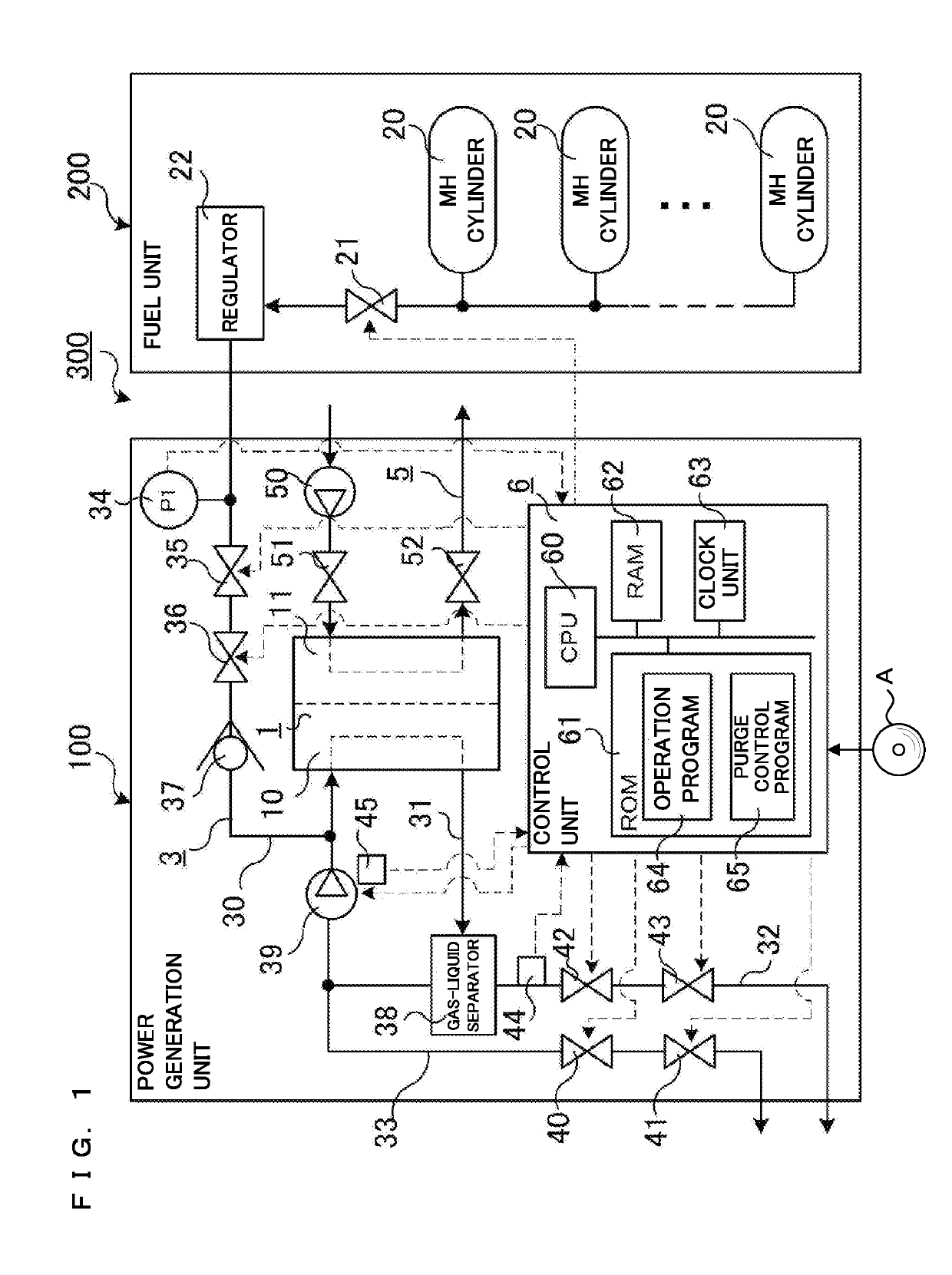
[0020]A fuel cell system 300 is provided with a power generation unit 100 and a fuel unit 200.

[0021]The power generation unit 100 is provided with a fuel cell stack 1, a hydrogen passage 3, an air passage 5, and a control unit 6. The fuel cell stack 1 will be hereinafter shortened as a stack 1.

[0022]The fuel unit 200 is provided with a plurality of MH (Metal Hydride) cylinders 20, a primary hydrogen shut-off valve 21, and a regulator 22. Each MH cylinder is filled with hydrogen absorbing alloy. The primary hydrogen shut-off valve 21 is connected with all MH cylinders 20 and is also connected with the regulator 22. The regulator 22 adjusts the hydrogen supply pressure. A reaction to occur when hydrogen absorbing alloy releases hydrogen is an endothermic reaction, and each MH cylinder 20 supplies hydrogen at a temperature equal to or higher than a predetermined tempera...

Example

Second Embodiment

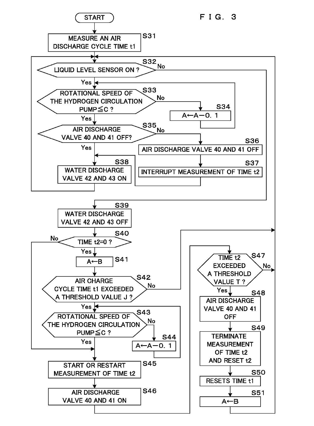
[0059]Next, Second Embodiment of the present invention will be described with reference to FIG. 3. Second Embodiment has process procedures of air discharge and water discharge different from First Embodiment. It is to be noted that the structure excluding the process procedures of air discharge and water discharge is similar to First Embodiment described above, and therefore detailed description thereof will be omitted.

[0060]FIG. 3 is a flowchart illustrating the process procedures of air discharge and water discharge by the CPU 60. In the initial state, the power generation unit 100 is performing power generation, and the air discharge valve 40, the air discharge valve 41, the water discharge valve 42, and the water discharge valve 43 are in a close state of energization OFF. The CPU 60 starts processing of air discharge and water discharge from such a state.

[0061]The CPU 60 causes the clock unit 63 to start measurement of an air discharge cycle time t1 (S31). Her...

Example

Third Embodiment

[0079]Next, Third Embodiment will be described with reference to FIGS. 4 and 5. Third Embodiment is different from First Embodiment in a feature that a second pressure gauge 46 and a third pressure gauge 47 are provided and in the process procedures of air discharge and water discharge. It is to be noted that the structure excluding the feature that a second pressure gauge 46 and a third pressure gauge 47 are provided and the process procedures of air discharge and water discharge is similar to First Embodiment, and therefore detailed description thereof will be omitted.

[0080]One end portion of a hydrogen circulation passage 31 is connected with an outlet side of an anode 10, while the other end portion is connected with a hydrogen supply passage 30. In the hydrogen circulation passage 31, a gas-liquid separator 38, a second pressure gauge 46, and a hydrogen circulation pump 39 are provided in this order from the outlet side of the anode 10. The second pressure gauge...


PUM


Abstract

An example of a fuel cell system comprises a fuel cell stack configured to react hydrogen and oxygen so as to generate electricity, a hydrogen supply passage for supplying hydrogen to the fuel cell stack, a hydrogen circulation passage for returning anode waste gas discharged from an anode of the fuel cell stack to the hydrogen supply passage, a hydrogen circulation pump that is provided at the hydrogen circulation passage, has an inlet and an outlet, and operates to circulate the anode waste gas, a waste gas discharge passage for discharging the anode waste gas to outside, the waste gas discharge passage being branched from a part of the hydrogen circulation passage between the anode and the inlet of the hydrogen circulation pump, a first discharge valve configured to put the waste gas discharge passage into an open state or a close state, a gas-liquid separator that is disposed at the hydrogen circulation passage and can separate a water component included in the anode waste gas, a water discharge passage for discharging the water component separated by the gas-liquid separator to outside, the water discharge passage being connected with the gas-liquid separator, a second discharge valve configured to put the water discharge passage into an open state or a close state, and a control unit configured to switch the first discharge valve and the second discharge valve into an open state or a close state, and the control unit performs control to deviate a period when the first discharge valve is in an open state and a period when the second discharge valve is in an open state from each other.

Description

CROSS-REFERENCE TO RELATED APPLICATIONS[0001]This application is a continuation application of PCT International Application No. PCT / JP2017 / 034675 which has International filing date of Sep. 26, 2017 and designated the United States of America, and claiming priority on Patent Application No. 2016-188064 filed in Japan on Sep. 27, 2016.FIELD[0002]The present disclosure relates to a fuel cell system comprising a fuel cell stack configured to electrochemically react hydrogen and oxygen so as to generate electricity, a hydrogen circulation passage through which anode waste gas discharged from the fuel cell stack is circulated, a hydrogen circulation pump provided at the hydrogen circulation passage, and a discharge valve configured to discharge anode waste gas to outside, to a control method of a fuel cell system, and to a computer program for executing control processing of a fuel cell system.BACKGROUND AND SUMMARY[0003]Some of fuel cell systems that obtain electromotive force by an el...

Claims


Application Information

Patent Timeline
IPC IPC(8): B60W10/28H01M8/04089H01M8/04746
CPCB60W10/28H01M8/04097H01M8/04753H01M8/04164H01M8/04179Y02T90/40Y02E60/50H01M8/04H01M8/10
Inventor FUKATSU, YOSHIAKI
Owner BROTHER KOGYO KK
Why Eureka
Try Eureka