Device For Securing At Least One Insulation On A Duct, Duct Equipped With Said Securing Device

a technology for securing devices and ducts, which is applied in the direction of ducting arrangements, lighting and heating apparatus, heating types, etc., can solve the problems of difficult to change the insulation, the embodiment is not fully satisfactory,

Active Publication Date: 2019-06-06
AIRBUS OPERATIONS (SAS)
View PDF0 Cites 1 Cited by
  • Summary
  • Abstract
  • Description
  • Claims
  • Application Information

AI Technical Summary

Benefits of technology

[0007]This securing device makes it possible to secure the insulating tube or tubes on the duct to be insulated without needing to glue them which makes it possible to change the insulating tubes without having to change the duct.
[0010]According to another feature, at least one of the first and second links comprises at least one guiding system, making it possible to guide the first and second ends relative to one another in a direction of introduction, and at least one locking system making it possible to immobilize the first and second ends in the direction of introduction.
[0015]According to one embodiment, the tongue has an inclined flat making it possible to deform the tongue to the deformed state when mounting the two parts of the securing device.
[0016]According to one configuration, at least one of the tenons comprises a slit which makes it possible to separate the tongue from the rest of the tenon in order for it to be able to be deformed between the rest and deformed states.

Problems solved by technology

This embodiment is not fully satisfactory because it is difficult to change the insulation without having to change the duct to which it is glued.

Method used


Image

  • Device For Securing At Least One Insulation On A Duct, Duct Equipped With Said Securing Device
  • Device For Securing At Least One Insulation On A Duct, Duct Equipped With Said Securing Device
  • Device For Securing At Least One Insulation On A Duct, Duct Equipped With Said Securing Device

Examples


first embodiment

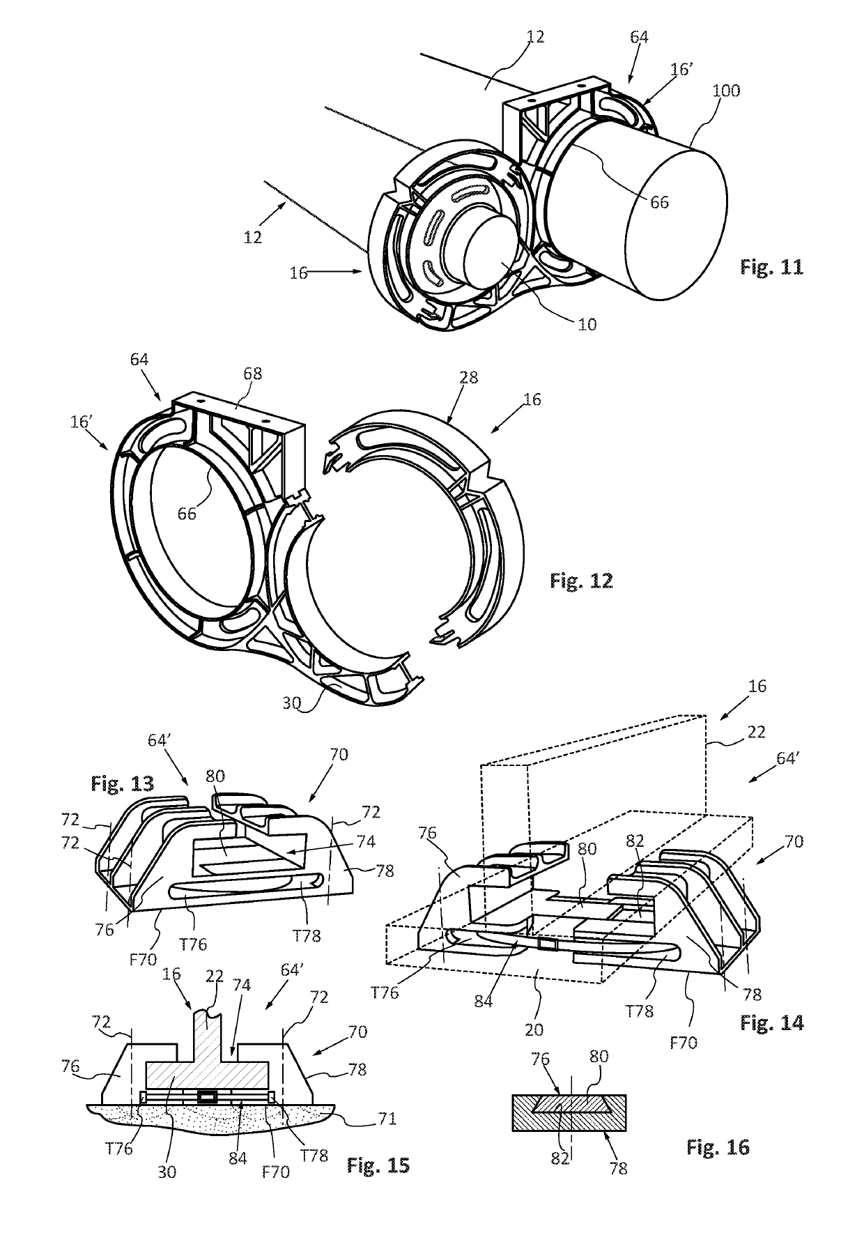
[0082] visible in FIGS. 11 and 12, the fixing system 64 is configured to link the duct 10 to a main duct 100.

[0083]According to this first embodiment, the fixing system 64 comprises a ring 66 linked to one of the parts 30 and configured to be fitted over the main duct 100.

[0084]According to this first embodiment, the fixing system 64 is incorporated in a second securing device 16′, the ring 66 fitted over the main duct 100 forming the inner ring of the second securing device 16′.

[0085]The outer ring of the second securing device 16′ can comprise a plate 68 making it possible to link to a support or a structure.

[0086]According to this first embodiment, the duct 10 is linked to a main duct 100 by two securing devices 16, 16′, the first securing device 16, surrounding the duct 10, being able to be dismantled and being produced in two parts 28, 30, the second securing device 16, fitted over the main duct 100, being produced in a single piece and comprising a system for fixing to a suppo...

second embodiment

[0087] visible in FIGS. 13 to 16, the fixing system 64′ is separate from the securing device.

[0088]According to this second embodiment, the fixing system 64′ comprises a body 70 which has a first contact surface F70, configured to be pressed and fixed by link elements 72 onto a support or a structure 71, and a T-shaped groove 74.

[0089]The T-shaped groove 74 is configured to receive the outer ring 20 of a securing device 16 and a part of its transverse web 22.

[0090]To adapt the fixing system to different dimensions of outer rings 20, the T-shaped groove 74 is adjustable. To this end, the body 70 comprises a first jaw 76 and a second jaw 78 which delimit the T-shaped groove 74 and which are configured to slide relative to one another in order to adjust the dimension of the T-shaped groove 74.

[0091]To this end, the first jaw 76 comprises an extension 80 with a trapezoidal section and the second jaw 78 comprises a groove 82 which has a form complementary to that of the extension 80 so t...


PUM


Abstract

A device for securing at least one insulating tube on a duct, includes an inner ring configured to be mounted on the duct, an outer ring coaxial to the inner ring, and a transverse web linking the inner and outer rings, the inner and outer rings and the transverse web forming two recesses, arranged on either side of the transverse web, each configured to receive an end of an insulating tube.

Description

FIELD OF THE INVENTION[0001]The present application relates to a device for securing at least one insulator on a duct and a duct equipped with said securing device.BACKGROUND OF THE INVENTION[0002]In an aircraft, some ducts, used for example to convey hot air, have to be insulated.[0003]To this end, a tubular insulation is positioned around the duct. To secure it in place, the inner face of the tubular insulation is glued onto the duct and an adhesive tape is wound around the tubular insulation.[0004]This embodiment is not fully satisfactory because it is difficult to change the insulation without having to change the duct to which it is glued.BRIEF SUMMARY OF THE INVENTION[0005]Aspects of the present invention may remedy the drawbacks of the prior art.[0006]An embodiment of the invention is a device for securing at least one insulating tube on a duct, characterised in that the securing device comprises an inner ring configured to be mounted on the duct, an outer ring coaxial to the...

Claims


Application Information

Patent Timeline
Patent Type & Authority Applications(United States)
IPC IPC(8): F24F13/02F16L59/135F16L59/14
CPCF24F13/0209F24F13/0263F16L59/135F16L59/14F16L59/12F16L59/20F16L3/1025F16L3/20F16L3/237F16L3/26
Inventor LOPEZ, JOSE
Owner AIRBUS OPERATIONS (SAS)
Why Eureka
Try Eureka