Method for producing a plate of a turbomachine

a technology of turbomachine and plate, which is applied in the direction of machines/engines, electrical-based machining electrodes, mechanical apparatus, etc., can solve the problems of undesired deformation of the turbine disk, long processing time, and high wear of the corresponding cutting tools such as broaching needles and milling cutters, so as to prevent the deformation of the disk or the disk from warping, the effect of preventing the deviation of the shape and preventing the deviation of the disk

Pending Publication Date: 2022-02-03
MTU AERO ENGINES GMBH
View PDF0 Cites 0 Cited by
  • Summary
  • Abstract
  • Description
  • Claims
  • Application Information

AI Technical Summary

Benefits of technology

[0007]Thus, the object of the present invention is to provide a method for producing receiving grooves in a disk of a turbomachine, by which method an efficient production of a corresponding disk is made possible while simultaneously preventing deviations in shape. In particular, a shaping of the disk that is as exact as possible with a precise arr

Problems solved by technology

Of course, the corresponding cutting tools such as broaching needles and milling cutters are subject to high wear, since the disks are usually formed of high-temperature resistant wrought alloys, such as nickel-based materials.
In material-removing processing or machining of the turbine disks, the individual receiving grooves for the blade roots are introduced individually, one after another, into the disk, which, on the one hand, causes a long processing time, and, on the other hand, may lead to the ci

Method used


Image

  • Method for producing a plate of a turbomachine
  • Method for producing a plate of a turbomachine

Examples


Embodiment Construction

[0023]Further advantages, characteristics and features of the present invention will be clarified in the following detailed description of the examples of embodiment. Of course, the invention is not limited to these exemplary embodiments.

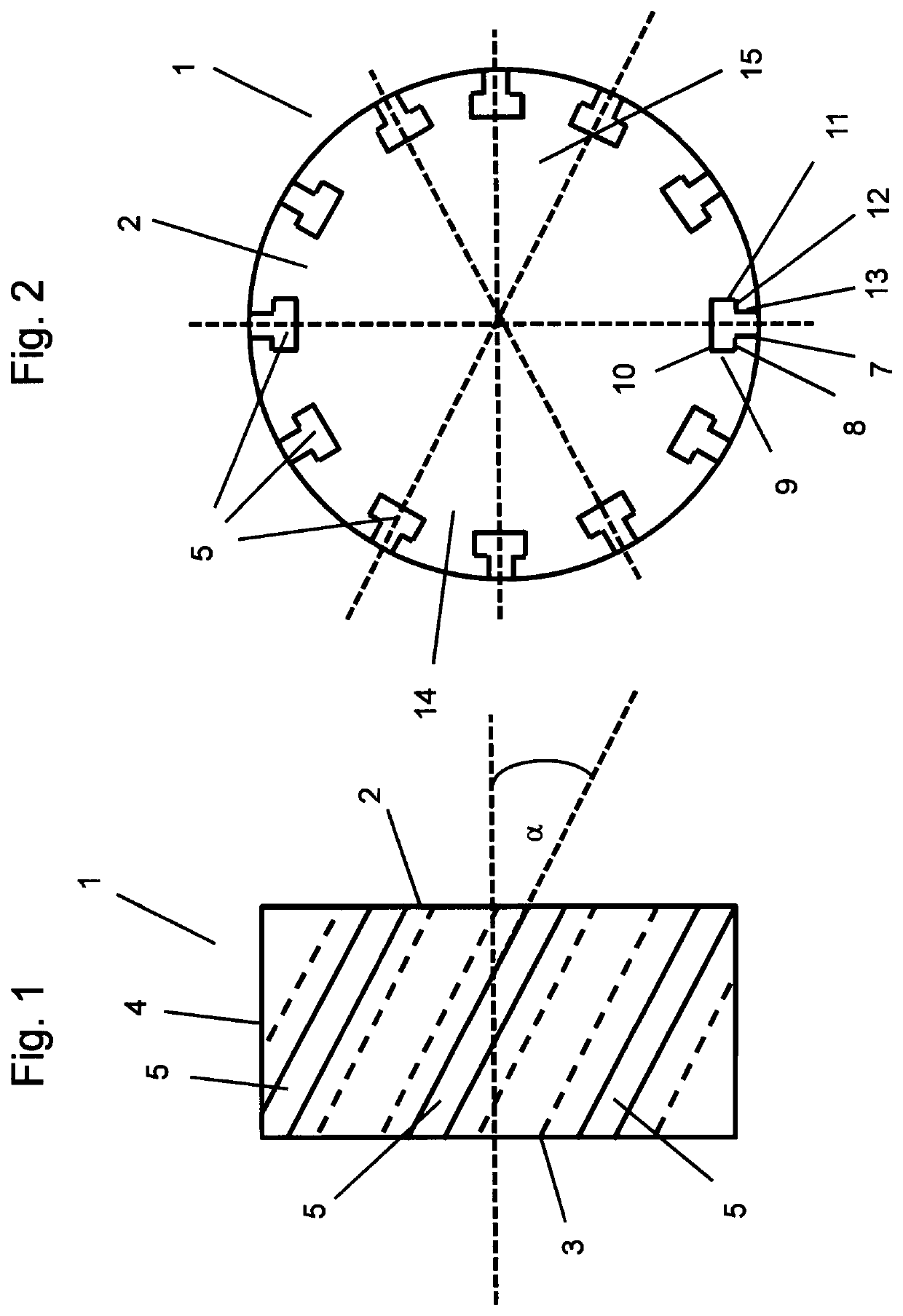
[0024]FIG. 1 shows a turbine disk 1, as it can be produced according to the present invention. The turbine disk 1 has a face 2 and an opposite-lying face 3, each of which is surrounded by a cylindrical peripheral surface 4 and which faces are connected to each other. A plurality of receiving grooves 5 are formed on the peripheral surface 4, and these serve for receiving blade roots of turbine blades (not shown). The receiving grooves 5 each have an expanded receiving space underneath the groove opening at the peripheral surface 5, as can be clearly recognized in FIG. 2 and are indicated by the dashed lines in FIG. 1. As results from the illustration in FIG. 1, the receiving grooves 5 are arranged with their longitudinal axes inclined by the angle a ...


PUM

PropertyMeasurementUnit
Residual stressaaaaaaaaaa

Abstract

The present invention relates to a method for manufacturing a plate of a turbomachine having a plurality of receiving grooves, which are formed on the cylindrical peripheral surface of the plate in order to receive blade roots of blades of the turbomachine. The receiving grooves extend in a straight line from one face of the plate to the other face of the plate, such that a straight line delimits the receiving groove from each point on the cross section of the receiving groove on one of the faces to the corresponding point on the cross section on the other face. A circular plate is provided and a plurality of receiving grooves are introduced into the plate simultaneously on opposing regions relative to a central axis of rotation of the plate.

Description

BACKGROUND OF THE INVENTIONField of the Invention[0001]The present invention relates to a method for producing a plate, in particular a turbine disk for a turbomachine, such as, for example, for a stationary gas turbine or an aircraft engine.Prior Art[0002]In turbomachines such as stationary gas turbines or aircraft engines, blades that interact with the through-flowing gas are often arranged in receiving grooves of plates or turbine disks, whereby blade roots of corresponding blades are provided for arrangement in the receiving grooves of the disk. Correspondingly, the receiving grooves and the blade roots of the blades have shapes that are complementary to one another. At the same time, for the secure fastening of the blade roots in the receiving grooves and for the load transfer from the blades to the disk, the receiving grooves and the blade roots may have complex contours, so that the manufacture both of the receiving grooves in the disks as well as the production of blade root...

Claims


Application Information

Patent Timeline
IPC IPC(8): B23H9/10B23H3/04F01D5/02
CPCB23H9/10F05D2230/11F01D5/02B23H3/04
Inventor PLATZ, ALBINBUSSMANN, MARTINGERLOFF, STEFFENFEILING, NICOLEKUEPPER, ANNA CARINAHUBER, NORBERTKLINGELS, HERMANN
Owner MTU AERO ENGINES GMBH
Why Eureka
Try Eureka