Flow Machine And Method For The Production Thereof

a technology of flow machine and flow control, which is applied in the direction of liquid fuel engine, mechanical apparatus, engine fuction, etc., can solve the problem of limited sound-damping effect of such a sound-damping element, and achieve optimal adjustment of so as to achieve optimal sound-damping characteristics and strength properties. optimal adjustment

Inactive Publication Date: 2019-06-13
MAN ENERGY SOLUTIONS SA
View PDF7 Cites 2 Cited by
  • Summary
  • Abstract
  • Description
  • Claims
  • Application Information

AI Technical Summary

Benefits of technology

[0005]According to one aspect of the invention, the stator, in the region of at least one flow passage, comprises at least one foam-like porous sound-damping element. Such a sound-damping element has good sound-damping characteristics while the same, furthermore, can be produced simply and cost-effectively.
[0007]Preferentially, the porosity of the respective foam-like sound-damping element is not equally distributed but locally different in terms of the number of pores and / or pore depth. The variation of the porosity is not solely dependent on the pore size but also on the material density with constant pore size. The variation of the pore size and pore shape also influences the porosity. By way of the different distribution of the porosity of the respective sound-damping element, the sound-damping characteristics and strength properties can be optimally adjusted.
[0009]According to an advantageous further development of the invention, walls, delimiting the respective flow passage and / or guide blades positioned in the respective flow passage are embodied as flow-like, porous sound-damping element at least in sections. This allows an optimal adjustment of sound-damping characteristics in the region of a stator-side flow passage of a turbomachine.

Problems solved by technology

The damping effect of such a sound-damping element is limited.

Method used


Image

  • Flow Machine And Method For The Production Thereof
  • Flow Machine And Method For The Production Thereof
  • Flow Machine And Method For The Production Thereof

Examples


Embodiment Construction

[0017]The invention relates to a turbomachine, in particular to a radial turbomachine. The invention, furthermore, relates to a method for producing such a turbomachine.

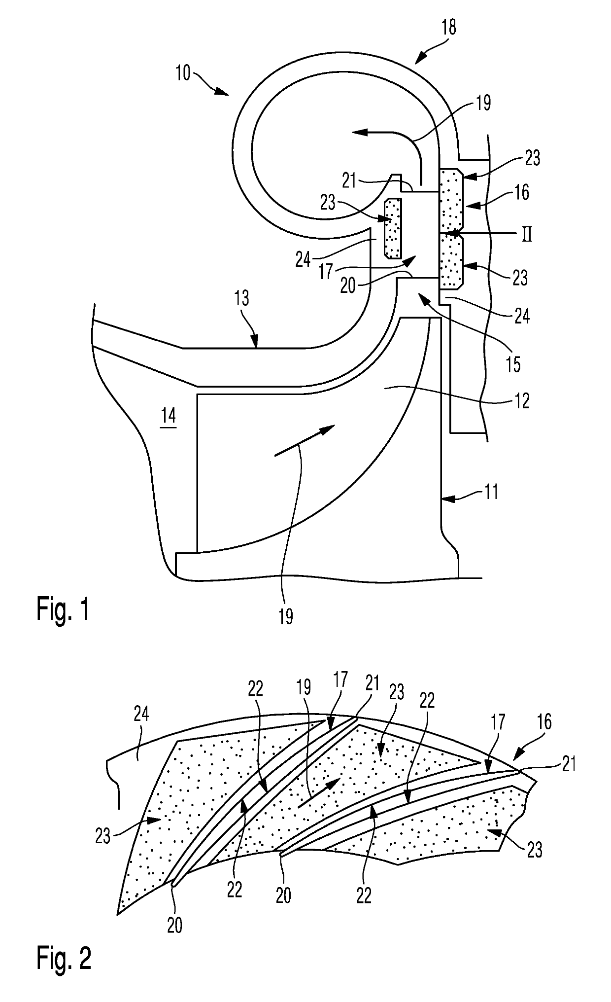
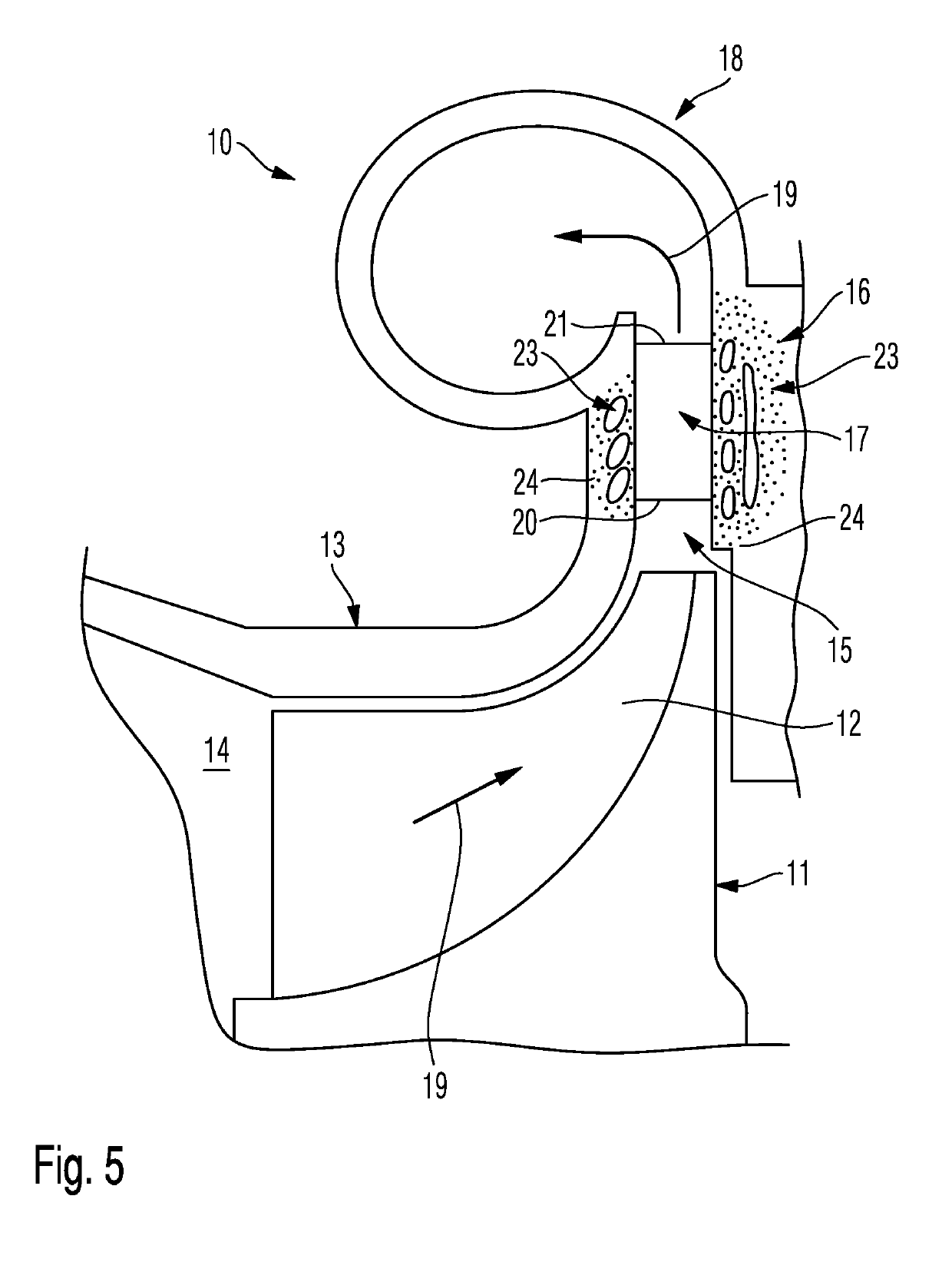
[0018]FIGS. 1 and 2 show different views of a turbomachine 10 designed as radial compressor.

[0019]The turbomachine 10 of FIGS. 1 and 2 formed as radial compressor comprises a rotor 11 with moving blades 12. Furthermore, the turbomachine 10 designed as radial compressor comprises a stator 13, wherein the stator 13 on the one hand delimits a flow passage 14 leading to the moving blades 12 of the rotor 11 extending in the axial direction on the other hand a flow passage 15 leading away from the moving blades 12 of the rotor 11 and extending in the radial direction, at least in sections.

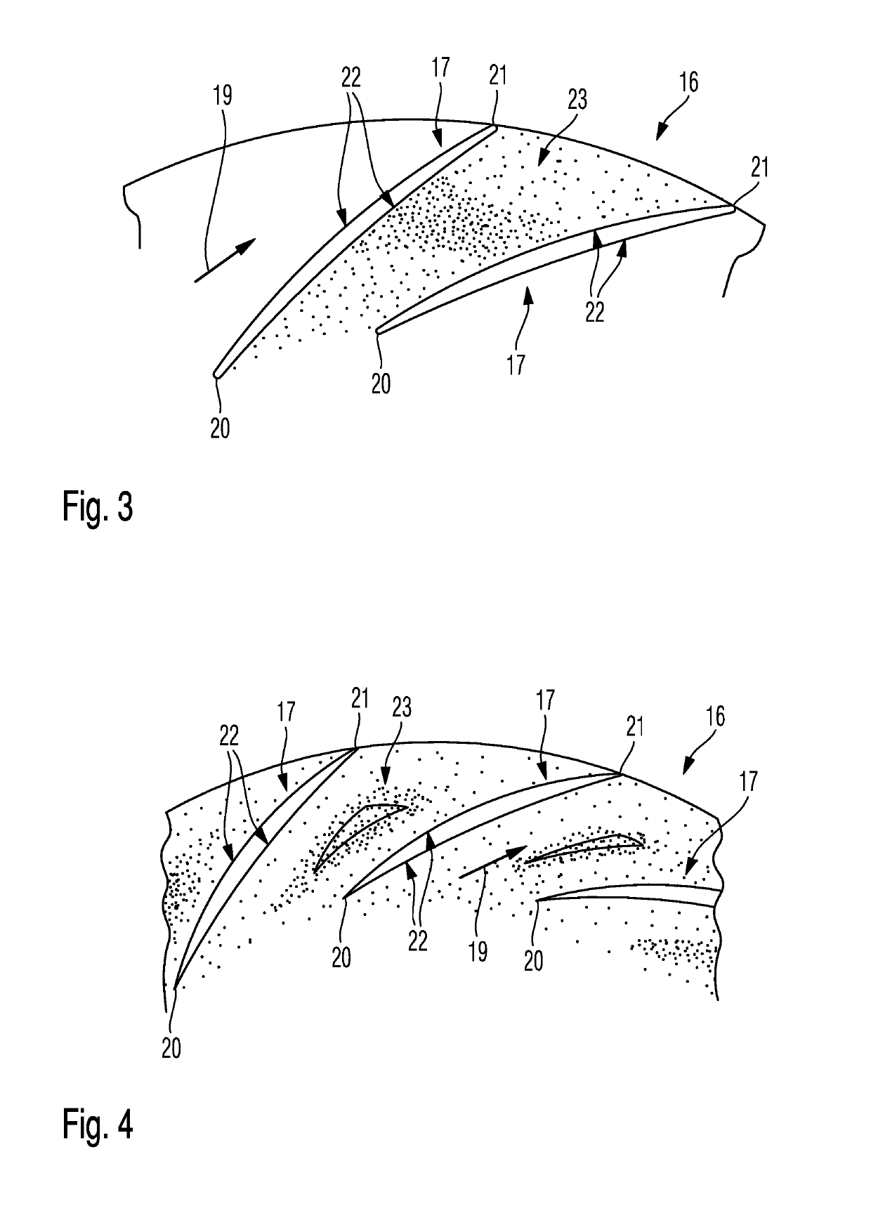
[0020]A diffuser 16 comprising guide blades 17 is part of the stator 13. Seen in the flow direction of the medium to be compressed, the guide blades 17 of the diffuser 16 are positioned downstream of the moving blades 12 of the rotor 11 i...


PUM

PropertyMeasurementUnit
sound-dampingaaaaaaaaaa
porosityaaaaaaaaaa
pore sizeaaaaaaaaaa

Abstract

The invention relates to a flow machine (10), in particular a radial compressor, comprising a rotor (11) with a rotor blade (12); a stator (13) with, preferably, a guide vane (17), the stator defining at least in sections, the at least one flow channel (14) leading to the rotor blades (12) of the rotor (11) and a flow channel (15) leading away from the rotor blades (12) of the rotor (11); the stator (13) comprising, in the region of at least one flow channel (14, 15) at least one foam-like porous sound damping element (23).

Description

CROSS REFERENCE TO RELATED APPLICATIONS[0001]This is a U.S. national stage of application No. PCT / EP2017 / 051976, filed on Jan. 31, 2017. Priority is claimed on German Application No. DE102016213296.2, filed Jul. 20, 2016, the content of which is incorporated herein by reference.BACKGROUND OF THE INVENTION1. Field of the Invention[0002]The invention relates to a turbomachine, in particular to a radial turbomachine, and to a method for producing the same.2. Description of the Prior Art[0003]From U.S. Pat. No. 6,669,436 B2 a turbomachine, namely a radial compressor, having a rotor comprising moving blades and a stator comprising guide blades is known. Seen in the flow direction of the medium to be compressed, the guide blades of the stator are designed as guide blades of a diffuser arranged downstream of the moving blades of the rotor. Accordingly, the guide blades are positioned in the region of a flow passage, which leads away from the moving blades of the rotor. From U.S. Pat. No. 6...

Claims


Application Information

Patent Timeline
Patent Type & Authority Applications(United States)
IPC IPC(8): F04D29/66F02C6/12
CPCF05B2240/10F05B2260/964F05B2230/21F05B2280/6012F02C6/12F05B2230/22F04D29/66F04D29/444F04D29/664F05D2300/514F05D2250/52F05D2230/31F04D29/406F04D29/4213F05D2260/96
Inventor BUSSOW, RICHARDKLAWES, ROBERT
Owner MAN ENERGY SOLUTIONS SA
Why Eureka
Try Eureka