Radar device for object identification

a technology of object identification and radar device, which is applied in the direction of measurement device, level indicator, instrument, etc., can solve the problems of high computational cost and time expenditure, inability to associate a detection signal with the presence of a specific object at a specific position, and high processing power and therefore expensive signal processors and/or microcontrollers, so as to quickly and efficiently determine the presence, quickly and efficiently check the receiving signal, and determine efficiently and quickly

Inactive Publication Date: 2019-06-13
VEGA GRIESHABER GMBH & CO
View PDF0 Cites 0 Cited by
  • Summary
  • Abstract
  • Description
  • Claims
  • Application Information

AI Technical Summary

Benefits of technology

[0009]The radar device according to the disclosure may in particular be configured for examining the receiving signal for the presence of the specified frequency merely and / or exclusively in the frequency portion of the measuring signal. In this case, the frequency portion may be small relative to an overall frequency spectrum of the receiving signal. For example, the frequency portion may be at most 75% of the frequency spectrum, in particular at most 50% of the frequency spectrum, and preferably between 1% and 25% of the frequency spectrum of the receiving signal. Evaluating the receiving signal in the frequency portion means that it is not necessary to evaluate the entire receiving signal by frequency and / or it is not necessary to determine a complete echo curve, but rather the receiving signal can be analysed only at the location and / or only in the frequency portion in which an echo is anticipated, owing to reflection of the transmission signal on the object. The radar device can essentially analyse whether or not the specified frequency is present in the receiving signal. Compared with complete evaluation of the receiving signal or determination of a complete echo curve, computational outlay and / or time expenditure can thus be saved. The radar device according to the disclosure can thus quickly and efficiently determine the presence of the specified frequency and / or the presence of the object. It is also possible, as a result, to dispense with expensive signal processors, control units and / or microcontrollers, and therefore the radar device can be manufactured in a cost-effective manner overall.
[0012]According to an embodiment of the disclosure, the control unit is configured to evaluate the receiving signal, for the specified frequency, in the frequency portion on the basis of a Goertzel filter. Alternatively or in addition, the control unit is configured to determine the presence of the specified frequency in the receiving signal using a Goertzel filter. Using a Goertzel filter can make it possible to quickly, efficiently, and reliably check the receiving signal for the presence of the specified frequency and thus for the presence of the object.
[0013]According to an embodiment of the disclosure, the control unit is configured to dismiss and / or hide all frequencies of the receiving signal outside the frequency portion. The control unit can therefore be configured to evaluate and / or analyse the receiving signal exclusively in the frequency portion. Alternatively or in addition, the control unit may be configured to examine the receiving signal exclusively for the presence of a single specified frequency. As a result, it is not necessary to analyse the receiving signal over the entire frequency spectrum thereof, but instead the presence of the specified frequency can be determined efficiently and quickly.
[0014]According to an embodiment of the disclosure, the control unit is configured to evaluate the receiving signal in a plurality of frequency portions and to determine whether a specified frequency is contained in the respective frequency portions. In this case, it is possible for the individual frequency portions not to overlap and / or to be mutually separated. As a result, it is possible to quickly and efficiently determine the presence of a plurality of different objects at different distances from the radar device.

Problems solved by technology

In order to detect the echo associated with the object and / or the limit level, existing radar devices or radar sensors calculate a complete echo curve by means of a Fourier transform, in particular by means of fast Fourier transform (FFT), which may be associated with high computational outlay and time expenditure.
This may also require high processing power and therefore expensive signal processors and / or microcontrollers.
Object identification is also often carried out using a continuous radar, it being possible in this case for all reflecting objects to generate a detection signal at different positions in the measuring range of the continuous radar, with the result that it is not possible to associate a detection signal with the presence of a specific object at a specific position.

Method used


Image

  • Radar device for object identification
  • Radar device for object identification

Examples


Embodiment Construction

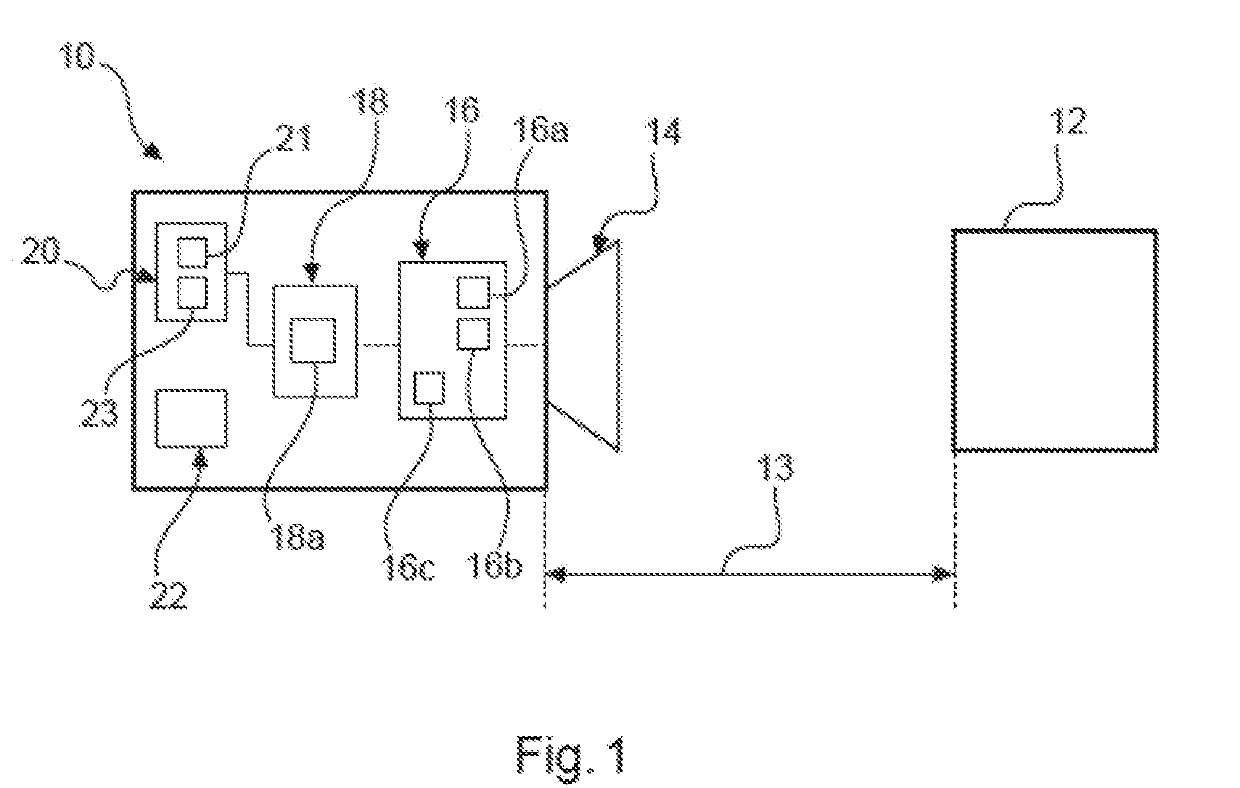
[0030]FIG. 1 shows a radar device 10 according to an embodiment of the disclosure. The radar device 10 is in particular configured for identifying an object 12, which is located at a distance 13 from the radar device 10 and / or is arranged at a spacing 13 from the radar device 10. In this case, the object 12 can in particular be a limit level of a medium, for example in a container, and / or a limit level of a channel. However, the object 12 can also be any other object.

[0031]The radar device 10 comprises an antenna 14 for transmitting and / or sending a transmission signal, a radar-based transmission signal, and / or a radar signal. The antenna 14 is furthermore configured for receiving a reflected signal and / or reflection signal. In order to generate the transmission signal, the radar device 10 may comprise a radar module for example.

[0032]The radar device 10 may in particular be configured as an FMCW radar 10. A frequency of the transmission signal can therefore be increased in a ramp-l...


PUM


Abstract

A radar device for identifying an object is provided, the radar device including at least one antenna configured to transmit a transmission signal and to receive a reflected signal; an evaluation circuit configured to determine a receiving signal based on the reflected signal; and a control unit configured to evaluate the receiving signal in a frequency portion of the receiving signal, and to determine whether a specified frequency that corresponds to a specific distance of the object from the radar device is contained in the frequency portion of the receiving signal.

Description

CROSS-REFERENCE TO RELATED APPLICATIONS[0001]This application claims the benefit of the filing date of German Patent Application No. 10 2017 222 272.7, filed on 8 Dec. 2017, the entire content of which is incorporated herein by reference.FIELD OF THE DISCLOSURE[0002]The disclosure generally relates to the field of object identification and / or limit level monitoring. The disclosure relates in particular to a radar device, such as a limit level radar device, for identifying an object and / or a limit level of a medium. The disclosure further relates to a method for identifying an object, using a radar device, a computer program element and a computer-readable medium.BACKGROUND OF THE DISCLOSURE[0003]Radar devices, such as Frequency Modulated Continuous Wave (FMCW) radar sensors, are frequently used for determining a fill level and / or limit level of a medium in a container. Radar devices can also be used for detecting an object and / or a limit level of a medium, it being possible for an e...

Claims


Application Information

Patent Timeline
Patent Type & Authority Applications(United States)
IPC IPC(8): G01S13/34G01S13/88G01S7/41
CPCG01S13/341G01S13/347G01S13/881G01S7/411G01F23/284G01S13/34
Inventor LAUN, ROBERT
Owner VEGA GRIESHABER GMBH & CO
Why Eureka
Try Eureka