Melt impregnation device and melt impregnation method

a thermoplastic resin and impregnation device technology, applied in the direction of coatings, etc., can solve the problems of affecting product quality, difficult to guarantee the balance of impregnating effect, and inability to uniformly impregnate multiple fiber bands, so as to achieve sufficient balanced impregnating effect of continuous fiber bands, increase flow velocity and pressure, the effect of enhancing the infiltration capacity of resin mel

Active Publication Date: 2019-06-20
KINGFA SCI & TECH CO LTD
View PDF0 Cites 3 Cited by
  • Summary
  • Abstract
  • Description
  • Claims
  • Application Information

AI Technical Summary

Benefits of technology

[0005]The present invention is to provide a melt impregnation device and a melt impregnation method, which can balance an impregnating effect of a continuous fiber band, can carry a broken fiber hairiness which is generated during the impregnation out of an impregnation area, and avoid a broken yarn, and to enhance a production stability and a production efficiency.
[0013]In the melt impregnation device and the melt impregnation method according to the present invention, the impregnation chamber with the corrugated shape for impregnating the continuous fiber band is formed between the lower surface of the upper die and the upper surface of the lower die, when the resin melt-distributing runner is connected with any peak position of the impregnation chamber, the chamber vertical height of the peak position of the impregnation chamber is larger than the chamber vertical height of the trough position of the impregnation chamber, and when the resin melt-distributing runner is connected with any trough position of the impregnation chamber, the chamber vertical height of the trough position of the impregnation chamber is larger than the chamber vertical height of the peak position of the impregnation chamber. Therefore, the resin melt can flow from a wide point of the corrugated impregnation chamber to a narrow point of the impregnation chamber, enormously increasing a flow velocity and a pressure of the resin melt, thus enormously enhancing an infiltration capacity of the resin melt infiltrating into the continuous fiber band, and guaranteeing a sufficiently balanced impregnating effect of the continuous fiber band. Meanwhile, owing to that both the lower surface of the upper die and the upper surface of the lower die have at least one peak and at least one trough, by using the corrugated impregnation chamber, the flow velocity and the pressure of the resin melt can be further enhanced, and an infiltrating impregnation capacity thereof can be enhanced. Since the impregnation capacity is enhanced, a drawing speed of the continuous fiber band can be increased, thus enhancing the production efficiency. Since the flow velocity and the pressure of the resin melt are enhanced, the continuous fiber hairiness in the impregnation chamber can also be carried out continuously, reducing accumulation of the continuous fiber hairiness, avoiding abrasion on the normal continuous fiber band, avoiding the broken yarn, and realizing a stable production. Besides, with help of the fiber pre-dispersion area to preheat and disperse the continuous fiber band, the subsequent resin melt would not be cooling-crystallized on a surface of the continuous fiber band, which facilitates the subsequent resin melt impregnating into the continuous fiber band more strongly, further guarantees sufficient and balanced impregnation of the continuous fiber band, improves the drawing speed of the continuous fiber band to a greater extent, and enhances the production efficiency.
[0014]When the resin melt-distributing runner is connected with the peak position of the impregnation chamber, the chamber vertical height of the peak position of the impregnation chamber is 4 mm-20 mm, and the chamber vertical height of the trough position is 2 mm-10 mm; and when the resin melt-distributing runner is connected with the trough position of the impregnation chamber, the chamber vertical height of the trough position of the impregnation chamber is 4 mm-20 mm, and the chamber vertical height of the peak position is 2 mm-10 mm. Therefore, in such range of the chamber vertical height, the flow velocity and the pressure of the resin melt can be enhanced to a greater extent, and thus the infiltration capacity of the resin melt is further improved.

Problems solved by technology

Currently, in a melt impregnation device for a continuous fiber-reinforced thermoplastic resin composite material, a continuous fiber bundle could not be melt impregnated uniformly, sufficiently and effectively due to an irrational structure of the melt impregnation device often, and thus a product quality is affected.
Although the number of the strip material may be increased, it is unlikely to guarantee a uniform impregnation of the multiple fiber bands when they are impregnated concurrently.
Therefore, after the drawing speed is increased, it's more difficult to guarantee a balance of the impregnating effect.
Thus, a fiber would be left on the first extrusion die 101 and the second extrusion die 102 during the movement of the fiber band, resulting in an easily broken yarn of the fiber band during being coated with the resin basis, affecting the product quality and decreasing a production efficiency.

Method used


Image

  • Melt impregnation device and melt impregnation method
  • Melt impregnation device and melt impregnation method

Examples


embodiment 1

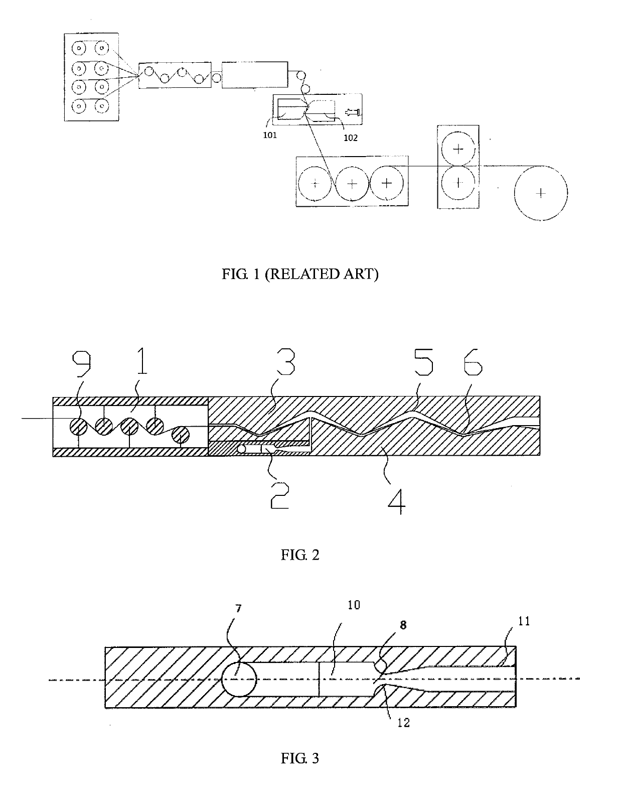
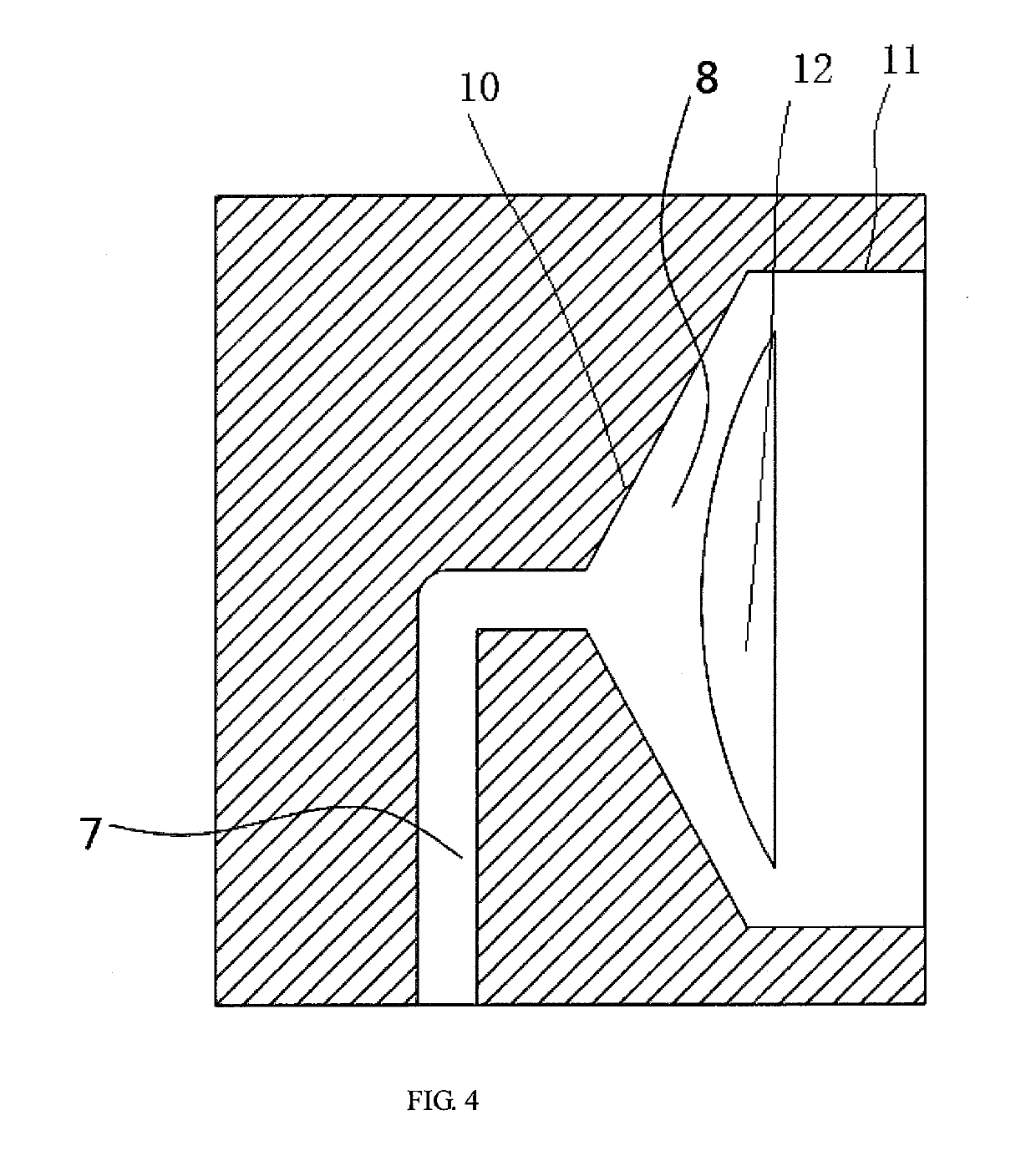
[0031]Single or multiple continuous fiber bands were introduced to a fiber pre-dispersion area 1. There were two tension roller sets in the fiber pre-dispersion area 1, and the continuous fiber band wound each tension roller 9 in the fiber pre-dispersion area 1 successively. The continuous fiber band was preheated and dispersed, and a temperature for preheating was 60° C. A diameter of the tension roller 9 was 50 mm, and a distance between the adjacent tension rollers 9 was 200 mm. A resin melt was injected into a resin melt-distributing runner 2 of a melt impregnation area, and then flowed into an impregnation chamber of an impregnation runner from the resin melt-distributing runner 2. The continuous fiber band, which was preheated and dispersed, was drawn to the impregnation chamber of the impregnation runner for impregnation. Both a lower surface of an upper die 3 of the impregnation runner and an upper surface of a lower die 4 had one peak 5 and one trough 6, with a radius of co...

embodiment 2

[0033]Based on Embodiment 1, the temperature for preheating the continuous fiber band was set as 400° C. The resin melt-distributing runner 2 was connected with the trough position of the impregnation chamber. The chamber vertical height of the trough position of the impregnation chamber was 4 mm, and the chamber vertical height of the peak position of the impregnation chamber was 2 mm. Other details were the same as Embodiment 1. The drawing speed under the circumstance without the broken yarn was tested as 47 m / min via the tachometer.

embodiment 3

[0034]Based on Embodiment 1, the temperature for preheating the continuous fiber band was set as 200° C. The chamber vertical height of the peak position of the impregnation chamber was 10 mm, and the chamber vertical height of the trough position of the impregnation chamber was 5 mm. A height difference between the chamber vertical height of the peak position and the chamber vertical height of the trough position of the impregnation chamber was 5 mm. Other details were the same as Embodiment 1. The drawing speed under the circumstance without the broken yarn was tested as 52 m / min via the tachometer.


PUM

PropertyMeasurementUnit
flare angleaaaaaaaaaa
temperatureaaaaaaaaaa

Abstract

The present invention discloses a melt impregnation device and a melt impregnation method. Through an impregnation chamber with a corrugated shape, when a resin melt-distributing runner is connected with a peak position of the impregnation chamber, a chamber vertical height of the peak position of the impregnation chamber is larger than a chamber vertical height of a trough position of the impregnation chamber, and when the resin melt-distributing runner is connected with the trough position of the impregnation chamber, the chamber vertical height of the trough position of the impregnation chamber is larger than the chamber vertical height of the peak position of the impregnation chamber. The present invention can balance an impregnating effect of a continuous fiber band, can carry a broken fiber hairiness which is generated during the impregnation out of an impregnation area, avoids a broken yarn, and enhances a production stability and a production efficiency.

Description

CROSS-REFERENCE TO RELATED APPLICATION[0001]This application claims the priority benefit of China application serial no. 201711367964.X, filed on Dec. 18, 2017. The entirety of the above-mentioned patent application is hereby incorporated by reference herein and made a part of this specification.TECHNICAL FIELD[0002]The present invention relates to a melt impregnation device and a melt impregnation method, and specifically relates to a melt impregnation device and a melt impregnation method for a continuous fiber-reinforced thermoplastic resin composite material.BACKGROUND[0003]Currently, in a melt impregnation device for a continuous fiber-reinforced thermoplastic resin composite material, a continuous fiber bundle could not be melt impregnated uniformly, sufficiently and effectively due to an irrational structure of the melt impregnation device often, and thus a product quality is affected. Besides, as an extensive application of a continuous fiber material, it is extremely urgent...

Claims


Application Information

Patent Timeline
Patent Type & Authority Applications(United States)
IPC IPC(8): B29B15/12B29C70/50B29B9/14
CPCB29B15/122B29C70/50B29B9/14B29K2101/12B29B9/02B29B15/125B29B15/14Y02E60/10B29C70/523B29C70/527B29C70/54
Inventor HUANG, XIANBOCHEN, CHUNHUALI, YONGHUAZHANG, CHAOLUO, ZHONGFU
Owner KINGFA SCI & TECH CO LTD
Why Eureka
Try Eureka